Exploring the JTAG interface of the 7-series Xilinx FPGA and Zener diode protection
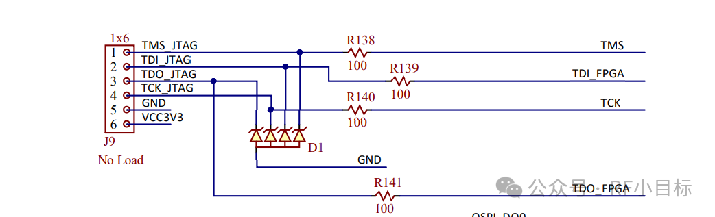
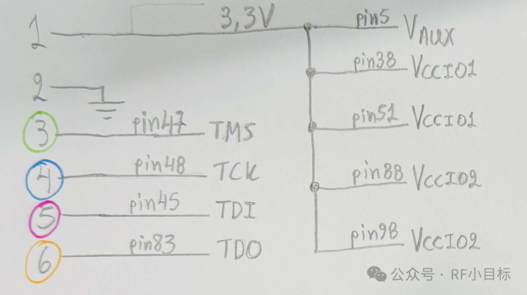
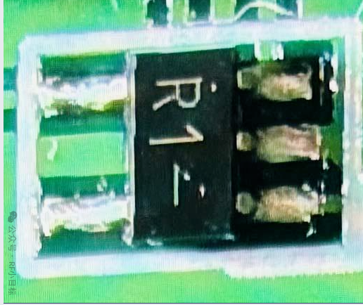
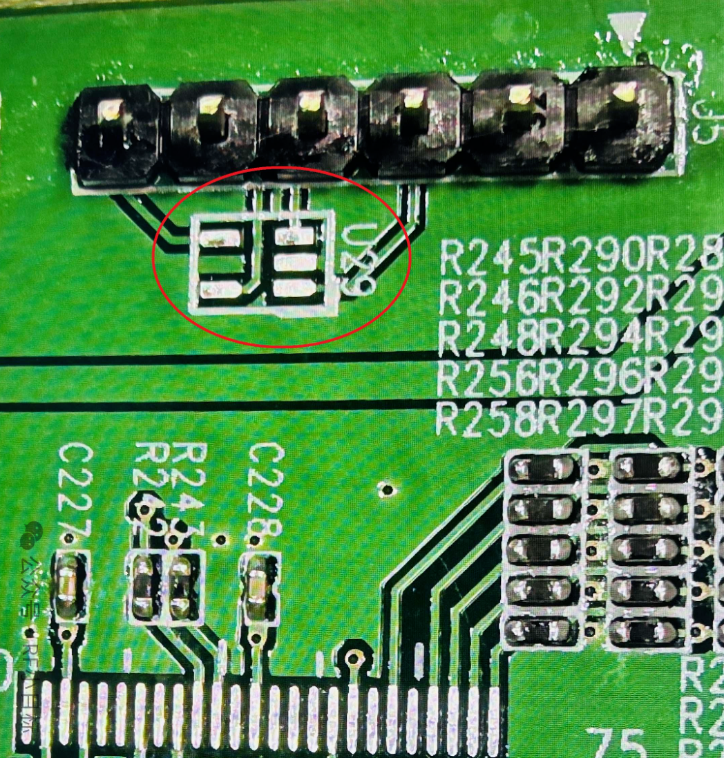
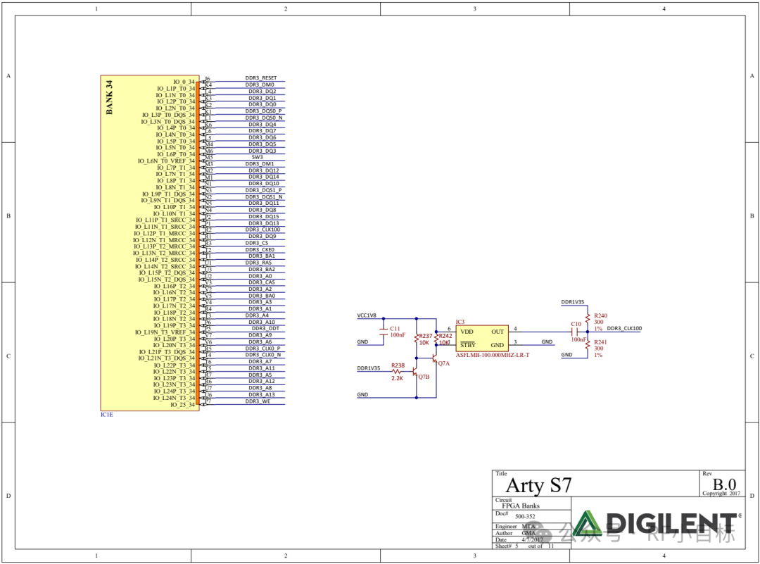
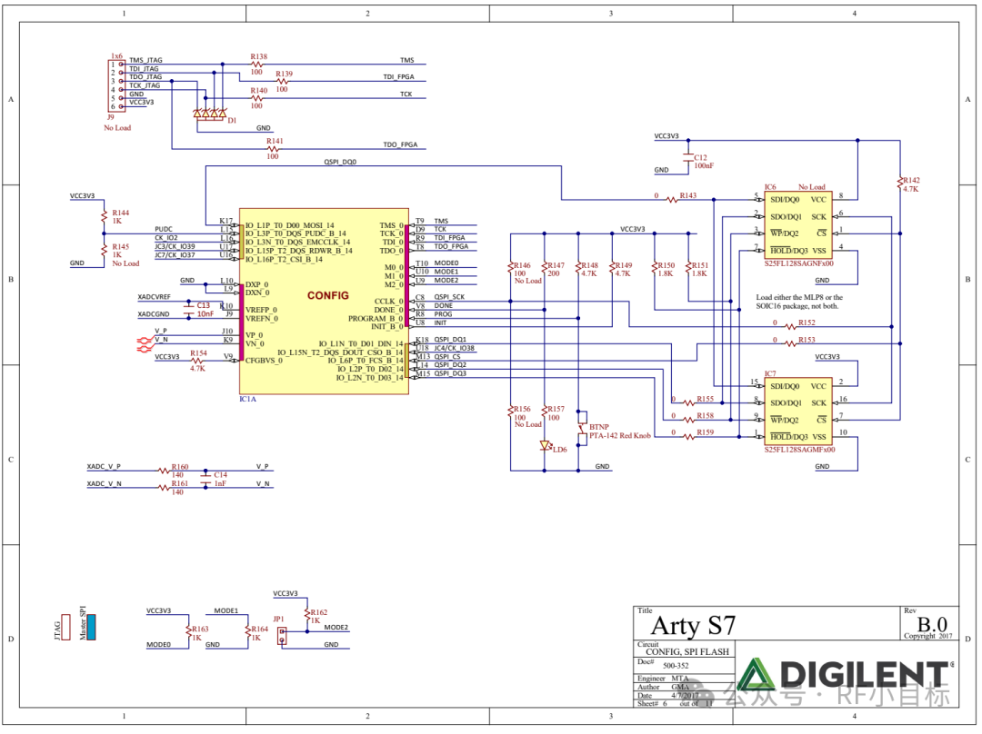
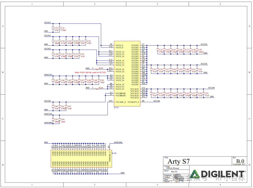
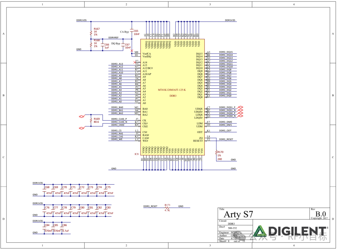
When I was selecting the 7-series Xilinx FPGA for a new PCB design, I was unsure about the design of the JTAG interface. To find a reliable reference, I reviewed several schematic diagrams of Xilinx evaluation boards, among which the schematic of the Arty S7 50 provided me with significant insights.
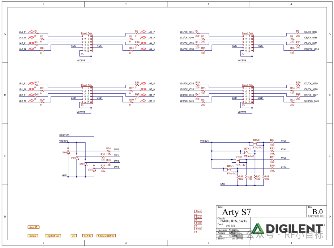
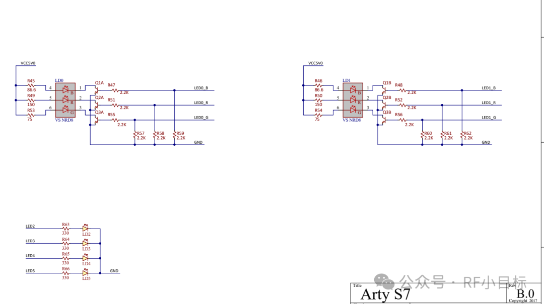
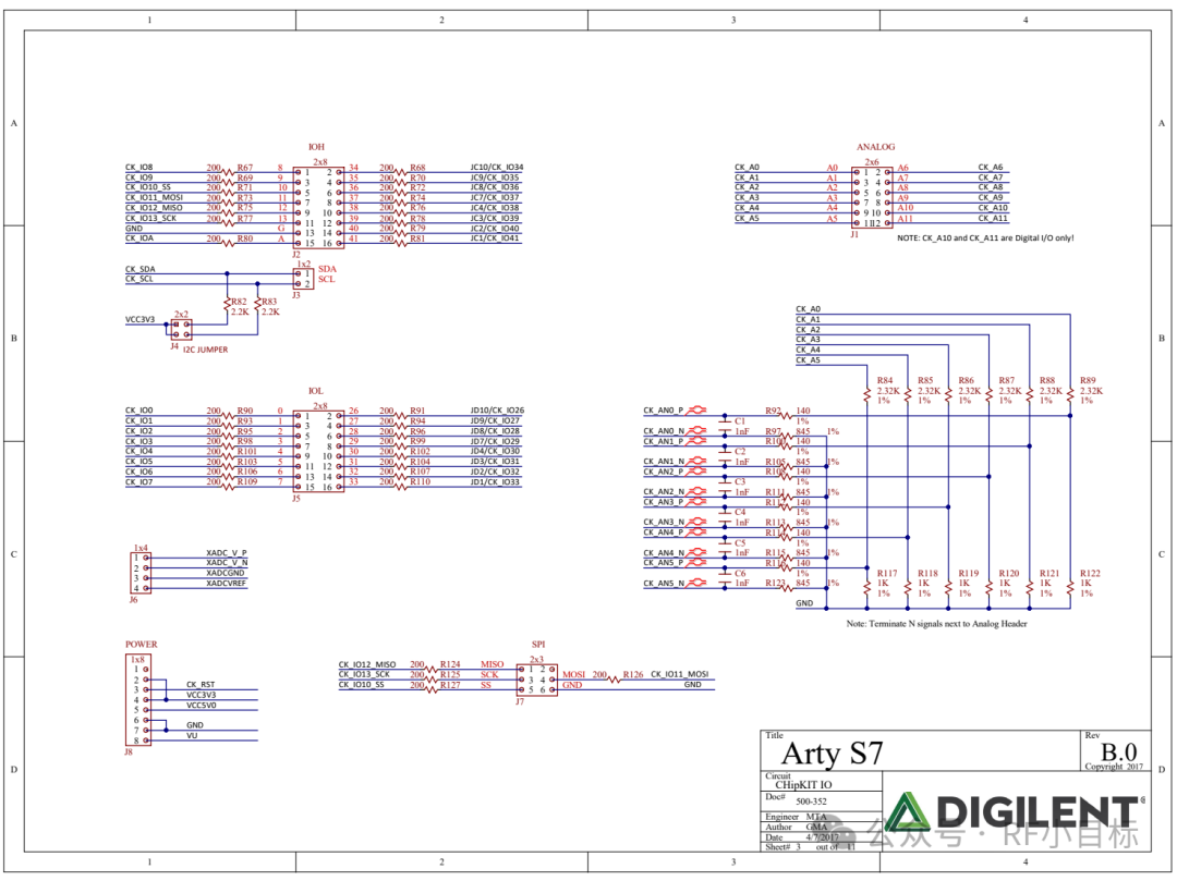
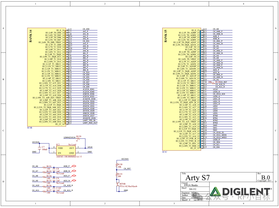
This page intentionally left blank.
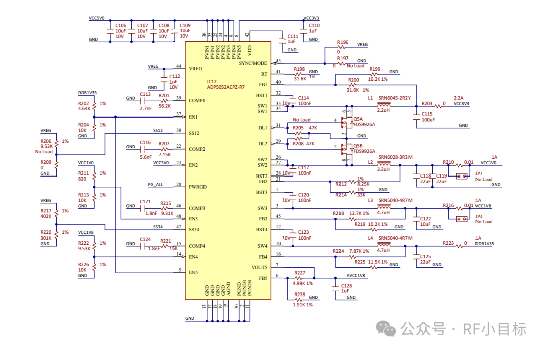
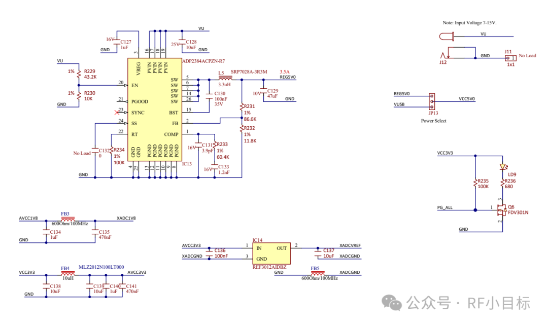
The JTAG interface of the Arty S7 50 has Zener diodes on page 6 of its schematic. I suspect the role of these Zener diodes is to protect the I/O from damage due to excessive voltage. Zener diodes have different breakdown voltages, and I estimate that the breakdown voltage of the Zener diodes in the diagram is greater than 3.3V. Based on this judgment, I believe that using Zener diodes with a breakdown voltage of around 5V should also be acceptable.
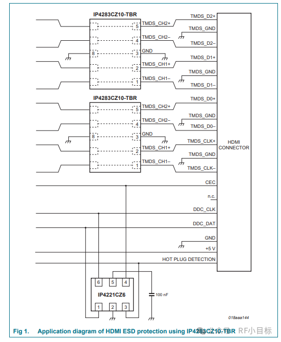
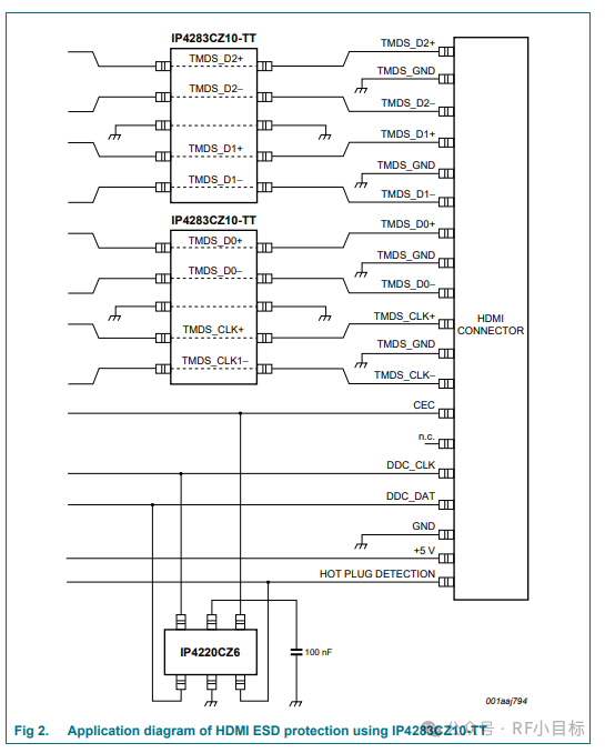
These Zener diodes are also known as TVS, or Transient Voltage Suppressors. They have different “trigger” voltages, and once this voltage is reached, they begin to conduct, capable of handling large currents in a very short time. However, the trigger voltage of a TVS is only an estimate, and there can be slight differences between devices. When they trigger, the voltage may still rise, and the greater the power of the triggering event, the more the voltage may increase. Taking a 3.3V “isolated” device as an example, it is designed to operate at 3.3V, and normally the TVS should not affect the circuit. Assuming a TVS has a trigger voltage of 4.5V, at this voltage, 1mA of current will flow through the TVS, and the current will increase non-linearly with the voltage. For instance, at 5V, there may be 10mA of current flowing, at 10V, 1A, and at 15V, it could even reach 10A. When selecting a TVS, it is crucial to thoroughly research and find the model with an appropriate clamping voltage. It is also important to understand that the voltage downstream of the TVS will exceed the trigger voltage when activated, and in the worst case, it may far exceed this value for a short time. Just like the spark generated by a finger, although the voltage is very high, the current is extremely small. The TVS can extinguish such sparks instantly, but during this process, the voltage on the pins may rise above the trigger voltage. Therefore, choosing the right TVS is critical to ensuring the stable operation of the JTAG interface.
Disclaimer: From the internet EEVBLOG
Previous Recommendations
Rocket Telemetry Transmitter – RF Section (449MHz)
DLUMM-30 (DLUMM-30) Servo Accelerometer
Understanding Spectrum Analyzers – Noise Figure
GH60-GeneHawk Handheld Signal Generator
Disassembling and Repairing Agilent N5182A MXG 100kHz – 3GHz Vector Signal Generator
Agilent N9020A (High Frequency Analysis)
“Agilent N9020A 10Hz – 8.4GHz Spectrum Analyzer Low Frequency Block Diagram: Module Analysis and Identifier Symbols from an Engineer’s Perspective”
“The Path to Advanced RF Microwave Signal Sources: The Evolution from HP, Agilent to SiLabs, In-Depth Analysis of E5052A and Exclusive Sharing from The Signal Path”
“The Path of RF Engineers: Disassembling Agilent 50GHz PSA (E4448A), Understanding ‘Look Twice, Imitate Once, Practice Thrice’, and Starting a New Journey in Understanding Attenuators”
Understanding RF Attenuators (The Best Companion for Instruments)