For beginners, RS485 may sound quite complex, but that’s not the case. I hope that after reading this article, you will find RS485 to be just a paper tiger.
1. UART Serial Communication
1.1 Serial Communication Connection Method
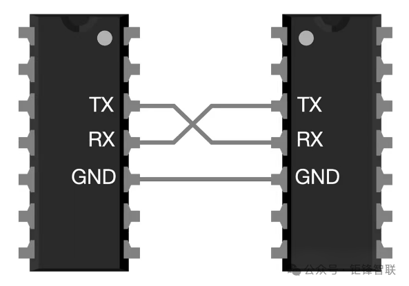
As shown in the figure, serial communication mainly relies on two wires to cross-connect TX and RX for data transmission and reception.
1.2 Serial Data Frame Format
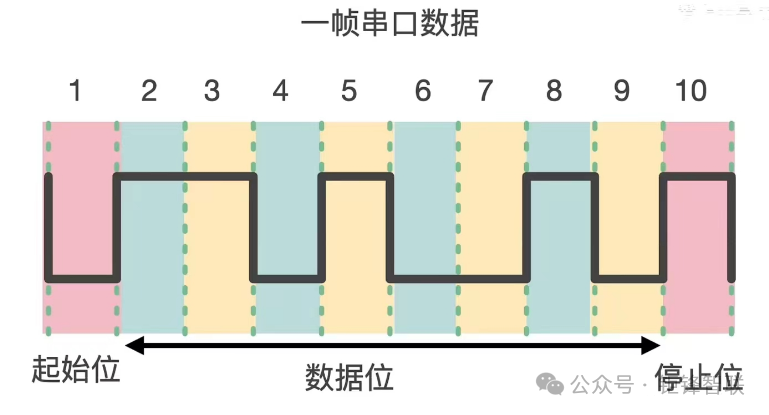
A frame of serial data typically consists of: 1 start bit + 8 data bits + 1 stop bit, totaling 10 bits. (The parity bit can be chosen by the user.)
1.3 Limitations of Serial Communication
1.3.1 Non-standard Electrical Interfaces
UART only defines the timing of signals without specifying the electrical characteristics of the interface; it does not standardize connectors for different devices, making connections between different devices via UART quite inconvenient.
1.3.2 Poor Anti-interference Capability
UART generally uses TTL signals to represent 0 and 1, but TTL signals have poor anti-interference capabilities, making data prone to errors during transmission.
1.3.3 Short Communication Distance
Due to the poor anti-interference capability of TTL signals, the communication distance is also very short, typically only suitable for communication between two chips on the same circuit board.
2. RS232 Communication
In serial communication, both parties must use a standard interface to facilitate communication between different devices. RS232 is currently the most commonly used serial communication interface.
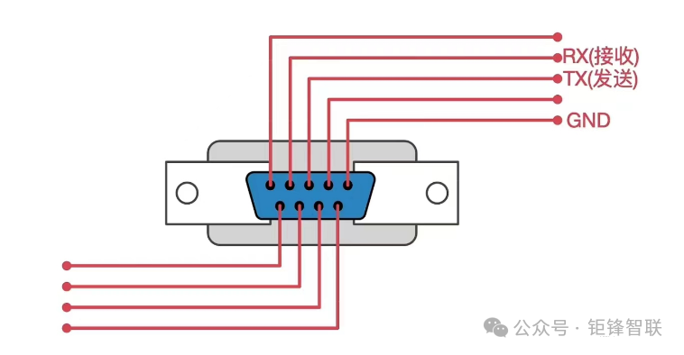
1.1 RS232 Communication Connection Method
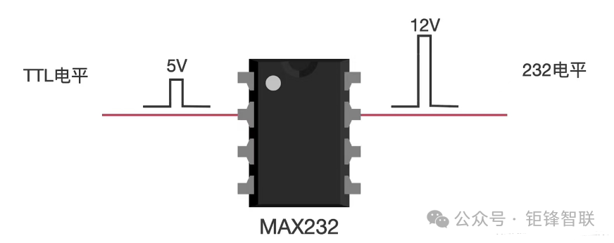
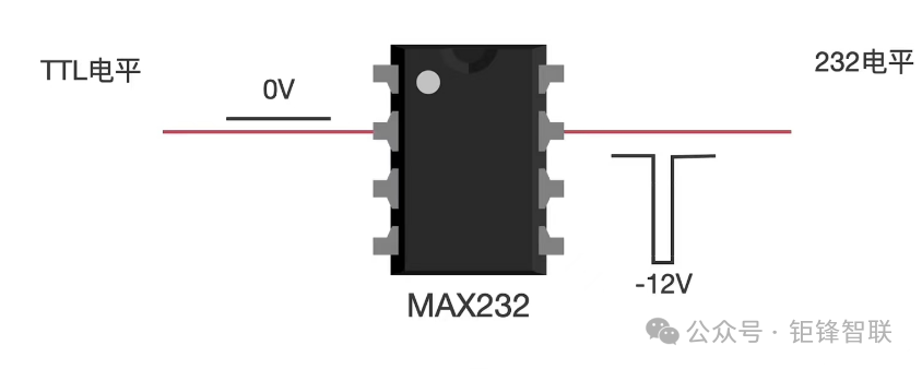
The RS232 communication method is based on serial communication, adding a 232 conversion chip to convert TTL levels to RS232 levels for communication.
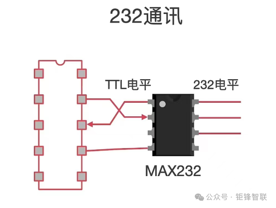
In serial communication, +5V is generally considered logic “1” and 0V as logic “0”.
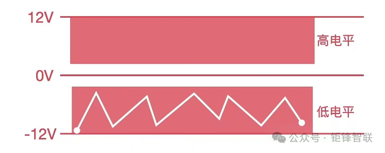
After the TTL level is converted to RS232 level by the 232 conversion chip, +12V is considered logic “1” and -12V as logic “0”.
Compared to TTL levels, RS232 levels have enhanced anti-interference capabilities, as shown in the figure. Even if interference signals cause level fluctuations, the high and low levels still have a significant margin of change.
1.2 RS232 Data Frame Format
RS232 simply converts the TTL levels of the serial port to RS232 levels, and its data frame format is consistent with that of the serial port.
1.3 Limitations of RS232
① The signal level values of the RS232 interface are relatively high, which can damage the interface circuit chips. Additionally, due to incompatibility with TTL levels, a level conversion chip is required to connect with TTL circuits.
② Although the anti-interference capability is improved compared to serial ports, the transmission distance is still limited, typically only usable up to about 15 meters.
③ The interface uses one signal line and one signal return line to form a common ground transmission method, which is prone to common-mode interference, making it weak against noise interference.
3. RS485 Communication
To address the issues present in serial communication and RS232 communication, the RS485 protocol was proposed. The RS-485 interface has excellent noise immunity, long transmission distances, and multi-station capabilities, making it the preferred serial interface. Since the RS485 interface typically requires only two wires for a half-duplex network, shielded twisted pair cables are used for transmission.
1.1 RS485 Communication Connection Method
The RS232 communication method is based on serial communication, adding a 485 conversion chip to convert TTL levels to RS485 levels for communication.
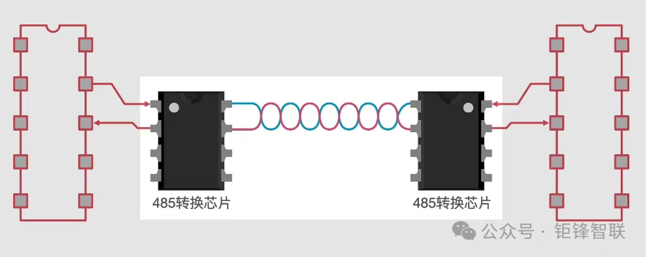
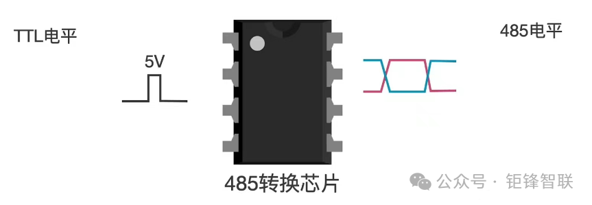
Signal: The RS485 standard specifies the use of differential signals (differential signals refer to using the voltage difference between two wires to represent 0 and 1) for data transmission, with a voltage difference of +2V to +6V representing logic “1” and a voltage difference of -2V to -6V representing logic “0”.
For example: A>B represents logic 0, B>A represents logic 1.
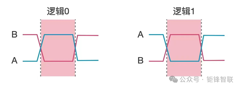
Using differential signals effectively reduces noise signal interference (because if interference occurs, both wires will be affected equally, so the voltage difference between the two wires can still correctly represent 0 or 1), extending the communication distance. The communication distance of RS485 can reach up to 1500m; the signal levels of the RS485 interface are lower than those of RS232, making it less likely to damage the interface circuit chips, and this level is compatible with TTL levels, allowing for easy connection with TTL circuits. As shown in the figure, the benefits of differential signals: even if the levels are interfered with, the difference remains largely unchanged.

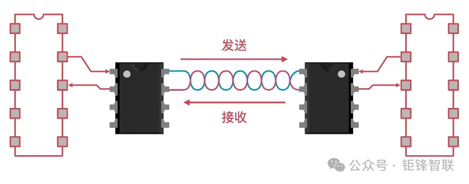
The interface uses a twisted pair cable as a bus to connect various nodes in series. The lead length from the bus to each node should be kept as short as possible to minimize the impact of reflected signals on the bus signal. Since a two-wire system (two twisted pairs) is used, both sending and receiving must use this pair of differential signal lines, so they cannot operate simultaneously, thus only half-duplex operation is possible.
Master-slave topology:

Half-duplex mode cannot send and receive simultaneously:
1.2 RS485 Data Frame Format
RS485 is also based on serial communication, with the frame format being the same as that of the serial port. Unlike serial and RS232, which differ only in electrical characteristics, the software programming is quite similar.
1.3 Advantages of RS485
① Long-distance transmission and multi-node connection: RS485 is a differential transmission communication method that supports long-distance transmission, typically reaching several kilometers (the specific distance depends on cable type, quality, and environmental conditions).
② High-speed data transmission: RS485 communication has a high data transmission rate, capable of supporting real-time data transmission, meeting the speed requirements of applications such as industrial automation.
③ Strong anti-interference capability: RS485 uses differential signal transmission, effectively resisting external electromagnetic interference, ensuring the stability and reliability of data communication.
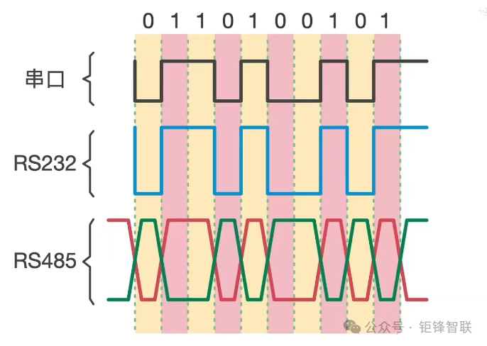
Lastly, let’s look at the differences in signals between serial, RS232, and RS485.
4. RS485 Programming
1.1 Transceiver SP3485 and Its Circuit Connection
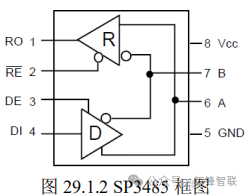
This article uses the SP3485 as the transceiver, which supports 3.3V power supply, a maximum transmission speed of up to 10Mbps, supports up to 32 nodes, and has output short-circuit protection.
-
The A and B bus interfaces in the figure are used to connect to the 485 bus.
-
RO is the receive output terminal, DI is the data input terminal for sending data.
-
RE is the receive enable signal (active low), DE is the send enable signal (active high).
The circuit diagram is shown below:
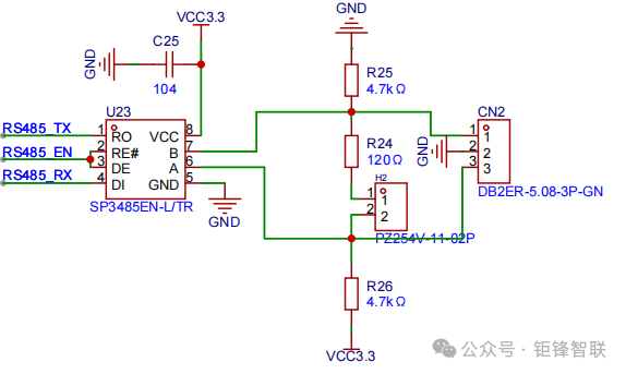
As shown, RE and DE are connected together to the same pin, controlling the high and low levels of this pin to change the transceiver’s send or receive mode: RS485_EN=1 indicates sending data. RS485_EN=0 indicates receiving data.
Note: When connecting two 485 interfaces, connect A to A and B to B.
As for the RS485 code part, it is quite similar to serial port initialization, and there are plenty of resources available online, so I won’t elaborate on it here.


Some screenshots from electronic books

Some screenshots from course PPTs

【Complete Set of Hardware Learning Materials】