
RS-232, RS-422, and RS-485 are serial data interface standards; communication issues are like traffic issues, with various situations such as high-speed, low-speed, congestion, interruptions, etc.
If we compare serial communication to traffic, UART to a station, then a frame of data is like a car. Cars on the road must obey traffic rules. In the city, the speed limit is generally 30 or 40, while on the highway, it can go up to 120. The road a car takes and the speed limit depend on how the protocol specifies it. What are the subtle differences between common serial protocols such as RS-232, RS-422, and RS-485? Let’s explore together.
01Explanation of RS232
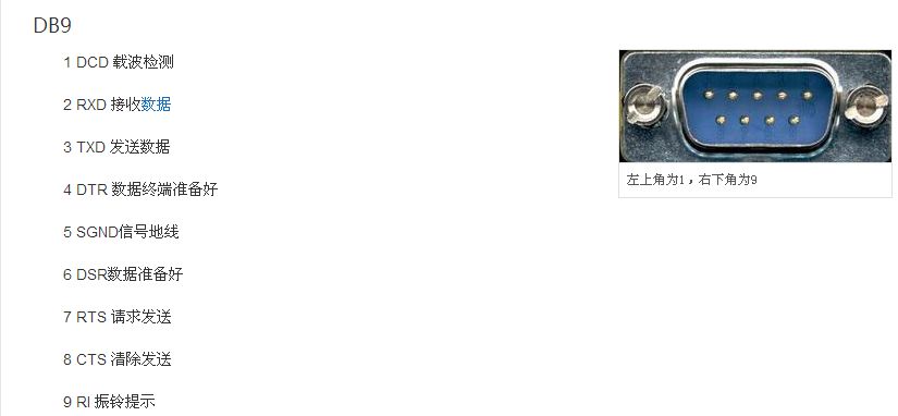
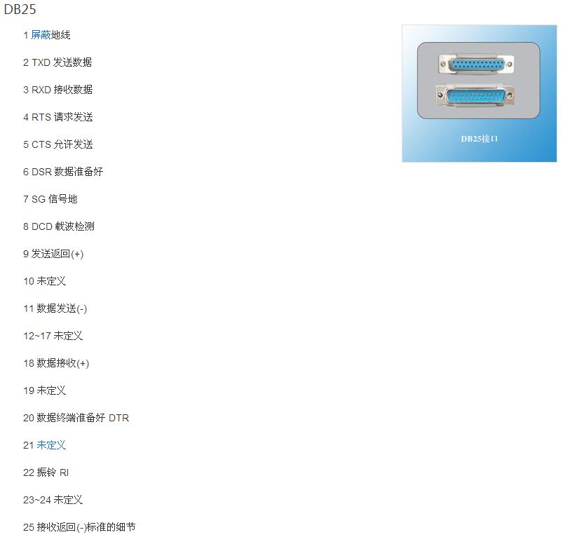
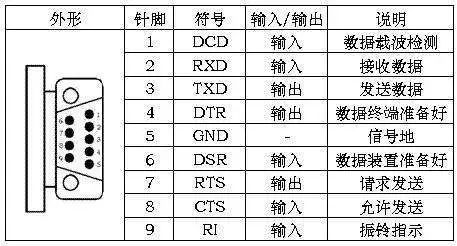
One of the communication interfaces on personal computers, it is an asynchronous transmission standard interface established by the Electronic Industries Alliance. Typically, the RS-232 interface appears in the form of 9 pins (DB-9) or 25 pins (DB-25). Generally, personal computers have two sets of RS-232 interfaces, referred to as COM1 and COM2.
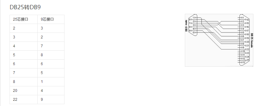
The RS232 electrical interface is divided into DB9 and DB25, defined as shown in the figure below:
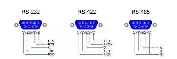
In fact, most of the time, not all interfaces need to be soldered; the simplified diagram is as follows:
02Explanation of RS422
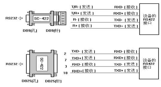
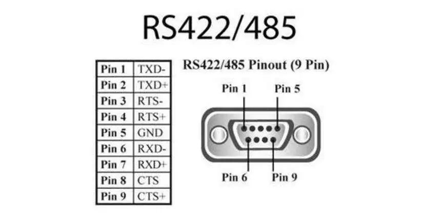
The full name of the RS-422 standard is “Electrical Characteristics of Balanced Voltage Digital Interface Circuits”; it defines the characteristics of the interface circuit. In fact, there is also a signal ground wire, making a total of five wires.
Due to the receiver using high input impedance and the sending driver having stronger driving capability than RS232, it allows multiple receiving nodes to be connected on the same transmission line, with a maximum of 10 nodes.
One master device and the rest are slave devices; slave devices cannot communicate with each other, so RS-422 supports point-to-multipoint bidirectional communication. The receiver input impedance is 4k, so the maximum load capacity at the transmitter is 10×4k+100Ω (termination resistance).
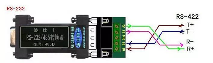
In fact, most of the time, not all interfaces need to be soldered; the simplified diagram is as follows:
03Explanation of RS485
RS-485, also known as TIA-485-A, ANSI/TIA/EIA-485, or TIA/EIA-485.
RS485 is a standard that defines the electrical characteristics of drivers and receivers in balanced digital multipoint systems, defined by the Telecommunications Industry Association and the Electronic Industries Alliance.
Digital communication networks using this standard can effectively transmit signals over long distances and in environments with high electronic noise. RS-485 makes it possible to configure inexpensive local networks and multi-branch communication links.
RS485 can be wired in two-wire or four-wire configurations; the four-wire configuration can only achieve point-to-point communication and is rarely used now. The more commonly used is the two-wire configuration, which is a bus topology structure, allowing up to 32 nodes to be connected on the same bus.
04Comparison of RS232, RS422, and RS485
All are serial communications, but used in different application scenarios
RS232 – 3-wire full duplex, point-to-point communication, transmission distance within 25 meters;
RS485 – 2-wire half duplex, point-to-multipoint master-slave communication, transmission distance can reach over 1200 meters;
RS422 – 4-wire full duplex, master-slave communication, transmission distance can reach over 1200 meters.
Thank you for your attention
For more electrical knowledge, please return to the public account and click on the article review!
ENDThis article comes from the internet. We focus on sharing, copyright belongs to the original author. For more project information, please click“Read the original text” ↓↓↓