Today, digital control technologies represented by PLC ladder diagrams are gradually replacing relays, which are products of the “bicycle era,” akin to “cars on the highway.” Although PLC ladder diagrams visually mimic the symbols of relay circuit diagrams (such as contactors, coils, etc.), their control logic has shifted from the “hardwired connections” of physical wiring to the “soft logic” of software programming. This seemingly subtle difference has brought about a qualitative change in industrial control efficiency and flexibility.

1. Essential Differences
- Relay Circuit Diagrams consist of physical relays, contactors, and other hardware, achieving logical control through hard wiring, with a limited number of contacts (usually 4-8 pairs), and modifications require rewiring.
- PLC Ladder Diagrams are based on software programming as “soft relays,” with logic stored in program form, allowing for unlimited reuse of contacts, and modifications can be made simply by editing the program.
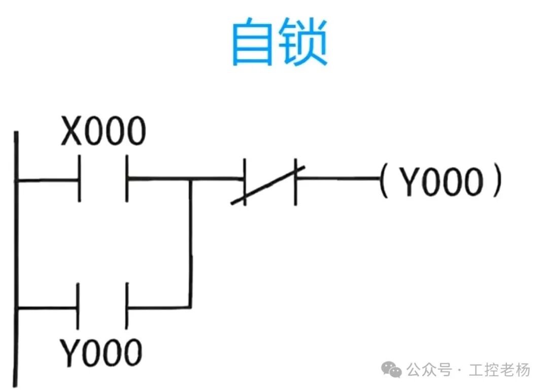

2. Core Differences Comparison Table
| Comparison Dimension | Relay Circuit Diagrams | PLC Ladder Diagrams |
|---|---|---|
| Composition | Physical components, hard wiring | Software programs, virtual soft components |
| Logic Modification | Requires disassembly and rewiring, time-consuming and labor-intensive | Directly modify the program, completed in 5 minutes |
| Reliability | Low (mechanical contact wear, short lifespan) | High (no-contact electronic components, long lifespan) |
| Function Expansion | Requires additional hardware, high cost | Only need to add program modules, low cost |
| Response Speed | Millisecond level (mechanical action) | Microsecond level (electronic signal) |

3. Summary of Applicable Scenarios
- Relay Circuits are suitable for simple control (such as lighting, single motor start-stop) and cost-sensitive scenarios.
- PLC Ladder Diagrams are suitable for complex logic (such as production lines, automated equipment) and scenarios that require frequent adjustments.
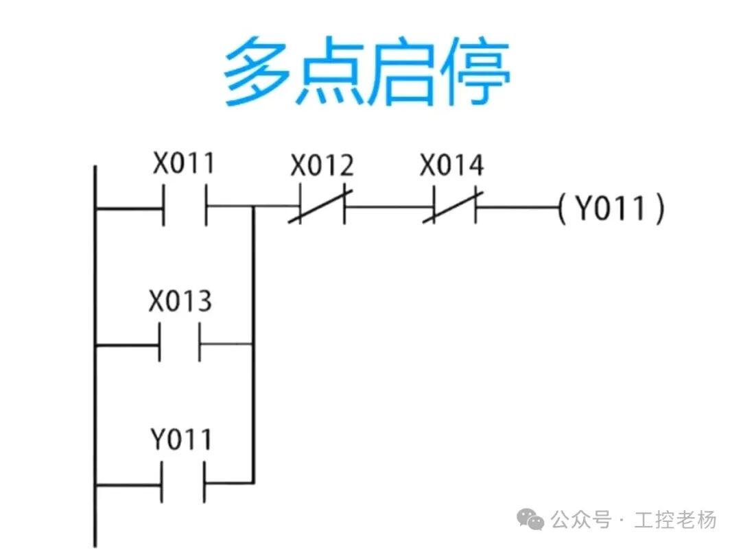

4. Troubleshooting Comparison: Efficiency Gap is Obvious
When a motor fails to start, the troubleshooting methods of the two control systems differ significantly:
- Relay Circuits require power disconnection and use of a multimeter to measure the continuity of SB1, SB2, KM contacts, and wires one by one, which may require disassembling the control cabinet, is time-consuming and prone to missed checks.
- PLC Systems can monitor the real-time status of X0, X1, Y0 online through programming software (such as whether X0 is ON, whether Y0 is output), and can locate the fault point within 30 seconds (for example, X1 normally closed contact sticking causing failure to start).
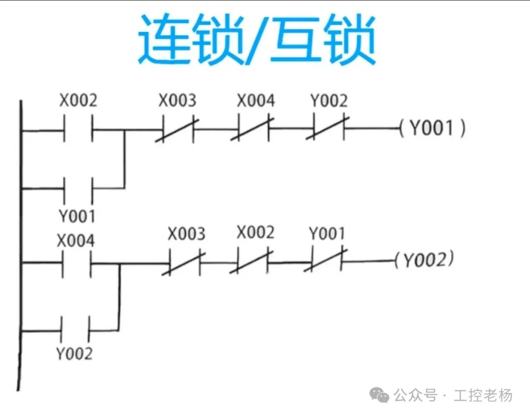

5. Suggested Learning Path
1: Solidify Electrical Control Basics (Introduction to Relay Circuits)
Focus on understanding the physical characteristics of normally open/normally closed contacts (such as state switching when a button is pressed) and the practical applications of self-locking and interlocking (such as interlocking design to prevent power short circuits in motor forward and reverse control).
2: Master the Conversion Skills from Relay Circuits to Ladder Diagrams
Conversion Mnemonic: “Soft replacement” for physical symbols, “table correspondence” for I/O addresses, “heavy left light right, more above less below” for logical structure, “right bus end” for coil output.
You can practice conversion through the “motor forward and reverse control” case: first draw the relay control circuit diagram, then convert it to a ladder diagram according to the above steps, comparing the differences in the implementation of “interlocking protection” (physical circuit uses normally closed contacts for hard interlocking, ladder diagram uses soft contact logic for interlocking).
3: Advance Logical Thinking through Simulation and Case Implementation
Prioritize practicing with simulation tools: Install GX WORKS2 (Mitsubishi) or Boto software (Siemens) to verify program logic without hardware conditions. For example, use timer T0 to implement “delay 5 seconds to start the motor,” monitor the “energy flow” changes through simulation, and observe the real-time updates of the timer’s current value (such as D8140 pulse count). For advanced practice, you can use self-developed practical software or Factory IO to build a 3D virtual scene, simulating the timing control of sensor detection and cylinder pushing in a “material sorting system.”
Relays, with their simplicity, reliability, and low cost, still hold a place in basic control scenarios with fixed logic; while PLCs, with their flexibility of software programming, high precision dynamic response, and strong integration capabilities, have become the core of complex automation systems. In practical applications, both can even work together—using PLCs to handle complex logical operations and relays to drive high-power actuators, collectively building an efficient and stable control system.
Previous Recommendations
Essential! These 30 PLC programming examples will take you from a novice to an electrical expert!
Stop taking detours! The 6 core modules that every electrician must master.
Frequency converter repair mnemonics and troubleshooting: 10 phrases to solve 90% of faults!
20 years of experience from a senior engineer: A complete guide to solving Siemens PLC problems.
Classic! Mitsubishi FX3U temperature control system case, to use PLC you must understand these cases!
Complete guide to Siemens 1200 PLC and V90 servo communication control: from configuration to programming implementation.
Save! Complete guide to Siemens G120 frequency converter parameter settings, one article is enough!
Design case sharing of intelligent three-dimensional parking garage monitoring system based on PLC and MCGS.
Why do others learn PLC so quickly? Grasp these 3 types of cases for ladder diagram entry, even beginners can learn after reading.
With this 120-page PPT for learning PLC, what else do you need to read “heavenly books”? 15 minutes to quickly get started with electrical control and PLC programming.
150 process flow diagrams compiled with effort: from symbols to simulation, the secret weapon for improving factory efficiency by 300%.
Mitsubishi PLC ladder diagram programming – a god-level guide, even beginners can understand, a must-read for novices.
Classic PLC programming examples, dual constant pressure water supply system from design to debugging: includes PLC program + wiring diagram + PID parameter table, learn it and you can use it!
Stop puzzling over circuits! These 187 diagrams, from start-stop control to overload protection, will save you 3 years of detours, a must-save for electricians!
Mitsubishi Works2 programming software beginner’s guide, even with no foundation you can easily get started!