1. Basics of RS232
RS-232-C is a serial physical interface standard established by the Electronic Industry Association (EIA) in the United States.
RS is the abbreviation for “Recommended Standard,” 232 is the identification number, and C indicates the revision number, representing the latest modification of RS232 (1969).
Prior to this, there were RS232B and RS232A. It was jointly developed in 1970 by the EIA in collaboration with Bell Systems, modem manufacturers, and computer terminal manufacturers as a standard for serial communication. Its full name is “Technical Standard for Serial Binary Data Exchange Interface Between Data Terminal Equipment (DTE) and Data Communication Equipment (DCE).”
1. Electrical Characteristics
EIA-RS-232C specifies the electrical characteristics, logic levels, and functions of various signal lines.
On TxD and RxD: Logic 1 (MARK) = -3V to -15V, Logic 0 (SPACE) = +3V to +15V. For control lines such as RTS, CTS, DSR, DTR, and DCD: Valid signal (on, ON state, positive voltage) = +3V to +15V; Invalid signal (off, OFF state, negative voltage) = -3V to -15V.
Depending on the power supply of the device, levels like ±5, ±10, ±12, and ±15 are possible.
2. Mechanical Characteristics of Connectors
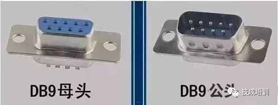
Since RS-232C does not define the physical characteristics of connectors, various types of connectors such as DB-25, DB-15, and DB-9 have emerged, each with different pin definitions.
Recently, the 8-pin RJ-45 connector has become increasingly common, although its pin assignments vary widely. The EIA/TIA 561 standard specifies a method for pin assignments, but the widely used Yost Serial Device Wiring Standard, invented by Dave Yost for Unix computers, and many other devices do not adopt any of the aforementioned wiring standards. The table below lists the signals and pin assignments commonly used in RS-232:
The signal labeling is from the perspective of the DTE device; TD, DTR, and RTS signals are generated by the DTE, while RD, DSR, CTS, DCD, and RI signals are generated by the DCE.
The RS-232 port on a PC is a 9-pin socket. Some devices connected to the PC’s RS-232 interface do not use the transmission control signals from each other and only require three interface lines: “Transmit Data TXD,” “Receive Data RXD,” and “Signal Ground GND.”
The bidirectional interface can be made with just three wires because all signals in RS-232 share a common ground. The unbalanced circuit makes RS-232 very susceptible to voltage offset issues between two devices.
For signal rise and fall times, RS-232 also has relatively poor control capabilities, making crosstalk problems easy to occur. RS-232 is recommended for communication over short distances (within 15m); due to the asymmetrical circuit nature, RS-232 interface cables are generally not made of twisted pairs.
3. Transmission Cables
The data transmission rate specified by the RS-232-C standard is 50, 75, 100, 150, 300, 600, 1200, 2400, 4800, 9600, 19200 baud per second, and the driver allows for a capacitive load of 2500pF, where communication distance will be limited by this capacitance.
For example, when using a communication cable with 150pF/m capacitance, the maximum communication distance is 15m; if the capacitance per meter is reduced, the communication distance can increase. Another reason for the short transmission distance is that RS-232 is a single-ended signal transmission, which has common-ground noise and cannot suppress common-mode interference, so it is generally used for communication within 20m.
According to the RS-232C standard, under the condition that the pulse distortion is less than 4%, the length of the transmission cable should be 50 feet; in practice, this 4% pulse distortion is very conservative, and in actual applications, about 99% of users operate within a pulse distortion range of 10-20%, so the maximum distance in practical use will far exceed 50 feet;
The American company DEC once stipulated a permissible pulse distortion of 10%, leading to the following experimental results. Cable No. 1 is a shielded cable, model DECP.NO.9107723, containing three pairs of twisted wires, each made of 22# AWG, and covered with shielding mesh. Cable No. 2 is an unshielded cable, model DECP.NO.9105856-04, which is a 22# AWG four-core cable.
4. Link Layer
In the RS-232 standard, characters are transmitted one after another as a series of bits. The most commonly used encoding format is the asynchronous start-stop format, which uses a start bit followed by 7 or 8 data bits, possibly a parity bit, and then two stop bits. Thus, sending a character requires 10 bits, which results in a good effect of making the overall transmission rate and sending signal rate divided by 10.
Serial communication requires multiple settings in software, with the most common settings including baud rate, parity, and stop bits. The baud rate refers to the rate at which bits are sent from one device to another, i.e., how many bits per second (bit/s).
Typical baud rates are 300, 1200, 2400, 9600, 19200, etc. Generally, both devices at the ends of communication should be set to the same baud rate, but some devices can also be set to automatically detect the baud rate.
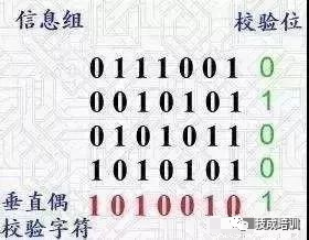
Parity is used to verify the correctness of data. Parity is generally not used, but if used, it can be either odd parity or even parity.
Parity works by modifying each sent byte (or limiting the bytes sent). If no parity is used, the data will not be changed.
In even parity, because the parity bit will be set to 1 or 0 (usually the highest or lowest bit), the data will be altered to make the total number of transmitted bits (including each bit of the character and the parity bit) even; in odd parity, the total number of transmitted bits (including each bit of the character and the parity bit) is odd.
Parity can be used by the receiving side to check whether transmission errors have occurred—if the number of “1” bits in a byte has changed, then that byte must have encountered an error during transmission. If the parity is correct, then either no errors occurred or an even number of errors occurred.
The stop bit is sent after each byte transmission, helping the receiving signal side’s hardware to resynchronize.
In serial communication software settings, D/P/S is the conventional symbol representation. 8/N/1 (very common) indicates 8-bit data, no parity, and 1-bit stop. Data bits can be set to 7, 8, or 9, and the parity bit can be set to none (N), odd (O), or even (E), with the parity bit using a bit from the data, so 8/E/1 indicates a total of 8 data bits, with one bit used for the parity bit. The stop bit can be 1, 1.5, or 2 bits (1.5 is used in teletypes at 60 wpm baud rate).
5. Transmission Control
When handshake signals or data integrity checks need to be sent, other settings need to be established. Common combinations include RTS/CTS, DTR/DSR, or XON/XOFF (in practice, instead of using connector pins, special characters are inserted into the data stream).
The receiving side sends XON/XOFF signals to the sending side to control when to send data; these signals are opposite to the direction of data transmission. The XON signal tells the sender that the receiver is ready to receive more data, while the XOFF signal tells the sender to stop sending data until the receiver is ready again. XON/XOFF is generally not recommended; it is recommended to use RTS/CTS flow control instead.
XON/XOFF is a method that works in-band between terminals, but both ends must support this protocol, and there is a possibility of confusion during sudden starts.
XON/XOFF can work over a 3-wire interface. RTS/CTS was originally designed for half-duplex cooperative communication between teletypes and modems, where only one side can send data at a time. The terminal must send a request to send signal and wait for the modem to respond with a clear send signal. Although RTS/CTS achieves handshaking through hardware, it has its own advantages.
6. Limitations of the RS-232 Standard
After many years of improvements in RS-232 devices and communication technology, the communication distance of RS-232 has greatly increased.
Since the RS-232 interface standard was established early on, it inevitably has shortcomings, mainly four points:
(1) The signal level values of the interface are relatively high, which can damage the interface circuit chips, and because it is not compatible with TTL levels, level conversion circuits are needed to connect with TTL circuits.
(2) The transmission rate is relatively low; in asynchronous transmission, the baud rate is 20Kbps. Now, due to the use of new UART chips like 16C550, baud rates have reached 115.2Kbps.
(3) The interface uses one signal line and one signal return line to form a common-ground transmission form, which is prone to common-mode interference, making it weak against noise interference.
(4) The transmission distance is limited, with the maximum standard transmission distance being 50 meters, but in reality, it can only be used at around 15 meters.
2. Basics of RS485
In response to the limitations of the RS-232 serial port standard, RS-422 and RS-485 interface standards have been proposed.
RS-485/422 uses balanced transmission and differential reception methods to achieve communication: the sending end converts the TTL level signal of the serial port into differential signals A and B, which are output, and after transmission through the cable, the differential signal is restored to TTL level signal at the receiving end.
Since the transmission line usually uses twisted pairs and is also differentially transmitted, it has a strong ability to resist common-mode interference, and the bus transceiver sensitivity is very high, able to detect voltages as low as 200mV. Therefore, transmission signals can be restored even over kilometers.
1. Electrical Characteristics of RS-485The driver can output a common-mode voltage of ±7V;The receiver’s input resistance RIN ≥ 12kΩ; Input capacitance ≤ 50pF.
With 32 nodes and 120Ω terminal resistance configured, the driver can still output a voltage of at least 1.5V (the size of the terminal resistance is related to the parameters of the twisted pair used).
On the sending end: Logic “1” is represented by a voltage difference of + (2 to 6)V between the two wires; Logic “0” is represented by a voltage difference of – (2 to 6)V. The input sensitivity of the receiver is 200mV (i.e., (V+) – (V-) ≥ 0.2V represents signal “0”; (V+) – (V-) ≤ -0.2V represents signal “1”).
2. Transmission Rate and DistanceThe maximum data transmission rate of RS-485 is 10Mbps, with a maximum communication distance of about 1219M. The transmission rate is inversely proportional to the transmission distance; at a transmission rate of 10Kb/S, the maximum communication distance can be reached.
However, since RS-485 often needs to communicate with the RS-232 port of a PC, in practice, the maximum is generally 115.2Kbps. Also, due to the high rate reducing the transmission distance, it is often around 9600bps or lower.
3. Network Topology
RS-485 interfaces use a combination of balanced drivers and differential receivers, enhancing the ability to resist common-mode interference, thus having good noise immunity. RS-485 operates in half-duplex mode and supports multipoint data communication.
The RS-485 bus network topology generally adopts a terminal-matched bus structure, meaning a single bus connects various nodes in series, and it does not support ring or star networks. If a star structure is needed, RS-485 repeaters or hubs must be used.
The RS-485/422 bus generally supports a maximum of 32 nodes. If special 485 chips are used, it can reach 128 or 256 nodes, with a maximum of 400 nodes supported.
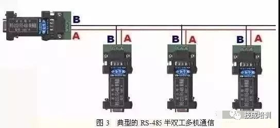
4. Connectors The international standard for RS-485 does not specify the connector standard for RS-485, so terminal blocks or DB-9, DB-25 connectors can be used.
3. Basics of RS422
The electrical performance of RS-422 is similar to RS-485. The main differences are:
(1) RS-485 has 2 signal wires: sending and receiving are both A and B. Since the reception and transmission of RS-485 share two wires, they cannot send and receive simultaneously (half-duplex).
(2) RS-422 has 4 signal wires: two for sending (Y, Z) and two for receiving (A, B). Since RS-422 separates reception and transmission, it can send and receive simultaneously (full-duplex).
(3) RS-422, which supports multi-machine communication, can be simply converted to RS-485 by shorting Y-A for RS-485’s A and shorting Z-B for RS-422’s B.
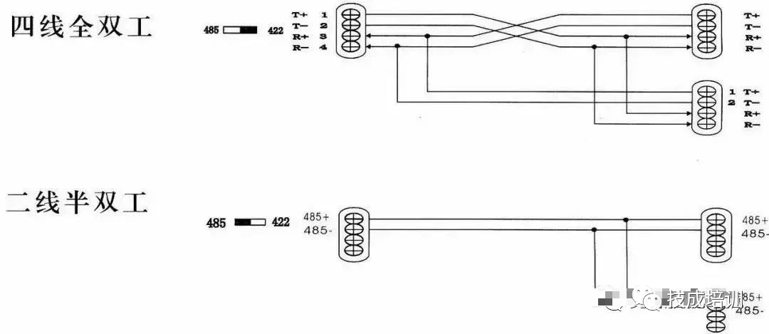
Many people often mistakenly believe that the RS-422 serial interface is the full-duplex version of the RS-485 serial interface; in fact, there are many differences in electrical characteristics between them, and the common-mode voltage range and receiver input resistance differences make the two standards suitable for different application fields.
The RS-485 serial interface driver can be used in RS-422 serial interface applications because the RS-485 serial interface meets all the performance parameters of the RS-422 serial interface, but the reverse does not hold.
For RS-485 serial interface drivers, the common-mode voltage output range is between -7V and +12V; for RS-422 serial interface drivers, this performance index is only ±7V. The minimum input resistance of RS-422 serial interface receivers is 4KΩ; while the minimum input resistance of RS-485 serial interface receivers is 12KΩ.
4. Basics of Serial Ports
A serial port is a very common communication protocol for devices on a computer (do not confuse it with Universal Serial Bus or USB).
Most computers contain two RS232-based serial ports. The serial port is also a common communication protocol for instrumentation and measurement devices; many GPIB-compatible devices also come with RS-232 ports. At the same time, the serial port communication protocol can also be used to obtain data from remote collection devices.
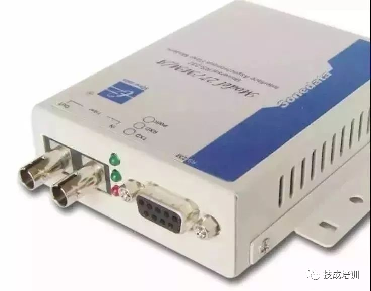
The concept of serial communication is very simple; the serial port sends and receives bytes bit by bit.
Although it is slower than parallel communication, which sends data byte by byte, the serial port can send data on one line while receiving data on another line. It is simple and can achieve long-distance communication. For example, when the IEEE488 defines parallel communication, it stipulates that the total length of the device line must not exceed 20 meters, and the length between any two devices must not exceed 2 meters; while for the serial port, the length can reach 1200 meters.
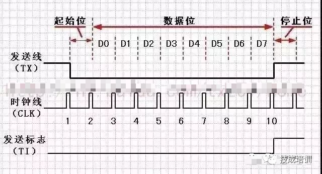
Typically, the serial port is used for the transmission of ASCII code characters.
Communication is accomplished using 3 wires: (1) ground, (2) transmit, (3) receive.
Since serial communication is asynchronous, the port can send data on one line while receiving data on another line. Other lines are used for handshaking but are not mandatory. The most important parameters of serial communication are baud rate, data bits, stop bits, and parity. For two ports communicating, these parameters must match:
1. Baud Rate
This is a parameter that measures communication speed. It indicates the number of bits transmitted per second. For example, 300 baud means 300 bits are sent per second. When we refer to the clock cycle, we mean the baud rate; for instance, if the protocol requires a baud rate of 4800, then the clock is 4800Hz. This means that the sampling rate on the data line for serial communication is 4800Hz. Typically, the baud rates for phone lines are 14400, 28800, and 36600. Baud rates can be significantly higher than these values, but baud rate is inversely proportional to distance. High baud rates are often used for communication between instruments placed very close together, a typical example being communication between GPIB devices.
2. Data Bits
This is a parameter that measures the actual data bits in communication. When a computer sends a data packet, the actual data will not be 8 bits; standard values are 5, 7, and 8 bits. How it is set depends on the information you want to transmit. For example, standard ASCII code is 0-127 (7 bits). Extended ASCII code is 0-255 (8 bits). If the data uses simple text (standard ASCII code), then each data packet uses 7 bits of data. Each packet refers to a byte, including start/stop bits, data bits, and parity bits. Since the actual data bits depend on the choice of communication protocol, the term “packet” refers to any communication situation.
3. Stop Bits
Used to indicate the last bit of a single packet. Typical values are 1, 1.5, and 2 bits. Since data is timed on the transmission line and each device has its own clock, there may be slight desynchronization between the two devices during communication. Therefore, the stop bit not only indicates the end of transmission but also provides an opportunity for computers to correct clock synchronization. The more stop bits that are suitable, the greater the tolerance for desynchronization between clocks, but the data transmission rate also slows down.4. Parity Bit
A simple error-checking method in serial communication. There are four types of error-checking methods: even, odd, high, and low. Of course, no parity bit is also acceptable. For even and odd parity, the serial port will set a parity bit (one bit after the data bits) to ensure that the number of logical high bits transmitted is even or odd.
For example, if the data is 011, then for even parity, the parity bit is 0, ensuring that the number of logical high bits is even. If it is odd parity, the parity bit is 1, resulting in 3 logical high bits. High and low bits do not truly check the data; they simply set the logical high or low parity. This allows the receiving device to know the state of a bit and provides an opportunity to determine whether noise has interfered with communication or whether the transmitted and received data are out of sync.
5. Basics of Handshaking
The RS-232 communication method allows simple connections with three wires: Tx, Rx, and ground. However, for data transmission, both sides must adopt the same baud rate for timing the data. Although this method is sufficient for most applications, it is limited in cases where the receiving side is overloaded. In this case, the handshaking function of the serial port is needed. In this section, we discuss the three most common forms of RS-232 handshaking:software handshaking, hardware handshaking, and Xmodem.1. Software Handshaking
The first type of handshaking we discuss is software handshaking. It is typically used when actual data is control characters, similar to the way GPIB uses command strings.
The necessary lines are still three:Tx, Rx, and ground, because control characters are indistinguishable from ordinary characters on the transmission line, the function SetXModem allows users to enable or disable the use of two control characters XON and OXFF. These characters are sent by the receiving side during communication to pause the sender.
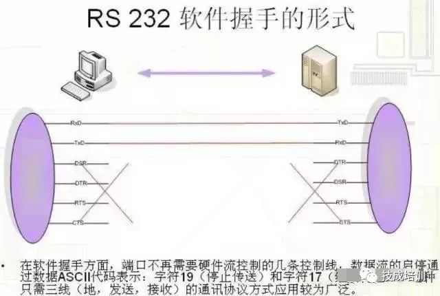
For example: suppose the sender is sending data at a high baud rate. During transmission, the receiver finds that the CPU is busy with other tasks, and the input buffer is full. To temporarily stop the transmission, the receiver sends XOFF, typically with a value of decimal 19, or hexadecimal 13, until the input buffer is empty. Once the receiver is ready to receive again, it sends XON, typically with a value of decimal 17, or hexadecimal 11, to continue communication.
When the input buffer is half full, LabWindows sends XOFF. Additionally, if the XOFF transmission is interrupted, LabWindows will send XOFF when the buffer reaches 75% and 90%. Clearly, the sender must follow this rule to ensure transmission continues.
2. Hardware Handshaking
The second type uses hardware line handshaking. Similar to Tx and Rx lines, RTS/CTS and DTR/DSR work together, one as output and the other as input.
The first set of lines is RTS (Request to Send) and CTS (Clear to Send).
When the receiving side is ready to receive data, it sets the RTS line high to indicate that it is ready; if the sender is also ready, it sets the CTS high to indicate that it will send data.
The second set of lines is DTR (Data Terminal Ready) and DSR (Data Set Ready).
These are mainly used for modem communication, indicating the status of the serial port and the modem. For example, when the modem is ready to receive data from the PC, it sets the DTR line high to indicate that the connection to the phone line has been established. Reading the DSR line as high indicates that the PC is starting to send data. A simple rule is that DTR/DSR indicates system communication readiness, while RTS/CTS is for the transmission of individual data packets.
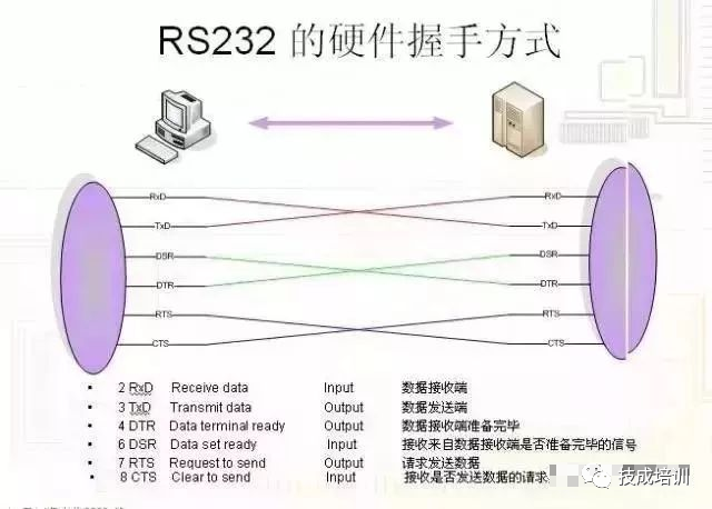
In LabWindows, the function SetCTSMode enables or disables hardware handshaking. If CTS mode is enabled, LabWindows follows these rules: when the PC sends data, the RS-232 library must detect that the CTS line is high before sending data. When the PC receives data, if the port is open and there is empty space in the input queue, the library function sets RTS and DTR high. If the input queue is 90% full, the library function sets RTS low but keeps DTR high. If the port queue is nearly empty, the library function sets RTS high but keeps DTR high. If the port is closed, the library function sets RTS and DTR low.
3. XModem Handshaking
The last handshaking we discuss is the XModem file transfer protocol. This protocol is very common in modem communication. Although it is typically used in modem communication, the XModem protocol can also be used directly in communication with other devices that follow this protocol.
In LabWindows, the actual XModem application is hidden from the user.
As long as the PC and other devices use the XModem protocol, the LabWindows XModem functions are used for file transfers.These functions are XModemConfig, XModemSend, and XModemReceive.
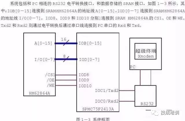
XModem uses parameters such as start_of_data, end_of_data, neg_ack, wait_delay, start_delay, max_tries, and packet_size.
These parameters need to be agreed upon by both parties in communication; the standard XModem has a standard definition; however, it can be modified through the XModemConfig function to meet specific needs. The usage of these parameters is determined by the neg_ack character sent by the receiving side. This notifies the sender that it is ready to receive data. It begins attempting to send, with a timeout parameter start_delay; when the timeout attempts exceed max_tries, or the sender receives start_of_data from the receiver, the sender stops trying.
If the sender receives start_of_data, the receiver will read the subsequent information data packet. The packet contains the packet number, the complement of the packet number as an error check, the actual data packet of packet_size bytes, and a checksum for further error checking.
After reading the data, the receiver will call wait_delay and then send a response to the sender. If the sender does not receive a response, it will resend the data packet until it receives a response or exceeds the maximum resend attempts max_tries.
If no response is received, the sender will notify the user that the data transmission has failed.
Since data must be sent in packets of packet_size bytes, when the last data packet is sent, if the data is not enough to fill a packet, it will be padded with ASCII NULL (0) bytes. This causes the received data to exceed the original data.
In XModem situations, do not use XON/XOFF, as the number of packets sent by the XModem sender may increase to the value of the XON/OFF control characters, leading to communication failure.
Thank you for your attention!
END1. This article is sourced from the internet, and does not represent the views and positions of the original author.The copyright of the published article belongs to the original author.2. We focus on sharing.If there is any infringement, please contact us for timely removal.Warm reminder:Long press the image to spread positive energy.