The RS-232 interface complies with the serial data communication interface standard set by the Electronic Industries Alliance (EIA) in the United States, originally designated as EIA-RS-232 (abbreviated as 232 or RS232). It is widely used for connecting computer serial interface peripherals.
RS-232 is one of the mainstream serial communication interfaces today. Due to the early emergence of the RS232 interface standard, it inevitably has some shortcomings, mainly as follows:
(1) The signal level values of the interface are relatively high, which can easily damage the chips of the interface circuit. The voltage of any signal line in the RS232 interface has a negative logic relationship. That is: logic “1” is -3 to -15V; logic “0”: +3 to +15V, with a noise margin of 2V. This means that the receiver must recognize signals above +3V as logic “0” and signals below -3V as logic “1”. TTL levels of 5V are considered positive logic, while 0 is negative logic. Since it is not compatible with TTL levels, a level conversion circuit is required to connect with TTL circuits.
(2) The transmission rate is relatively low; during asynchronous transmission, the baud rate is 20Kbps.
(3) The interface uses one signal line and one signal return line to form a common ground transmission method, which is susceptible to common-mode interference, resulting in weak noise immunity.
(4) The transmission distance is limited, with a maximum standard transmission distance of 50 feet, but in practice, it can only be used for about 15 meters.
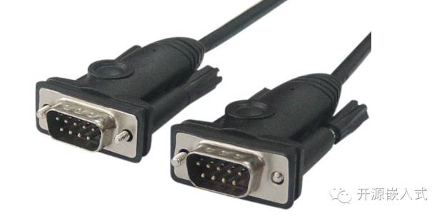 There are two types of RS-232 serial ports: the first type is DB9; the second type is DB25. Below is a description of each.
DB9 interface wiring instructions:
1 DCD Carrier Detect
2 RXD Receive Data
3 TXD Transmit Data
4 DTR Data Terminal Ready
5 SGND Signal Ground
6 DSR Data Set Ready
7 RTS Request to Send
8 CTS Clear to Send
9 RI Ring Indicator
DB25 interface wiring instructions:
1 Shield Ground
2 TXD Transmit Data
3 RXD Receive Data
4 RTS Request to Send
5 CTS Clear to Send
6 DSR Data Set Ready
7 SG Signal Ground
8 DCD Carrier Detect
9 Transmit Return (+)
10 Undefined
11 Data Transmit (-)
12~17 Undefined
18 Data Receive (+)
19 Undefined
20 Data Terminal Ready (DTR)
21 Undefined
22 Ring Indicator (RI)
23~24 Undefined
25 Receive Return
In practical applications, the most commonly used is the DB9 interface. If you encounter a DB25 interface, you can convert it by changing the wiring method. Wiring method from DB25 to DB9.

In the RS-232 standard, characters are transmitted in a serial manner as a string of bits. The advantage is fewer transmission lines and simple wiring, allowing for longer transmission distances. The most commonly used encoding format is the asynchronous start-stop format, which uses a start bit followed by 7 or 8 data bits, then an optional parity bit, and finally one or two stop bits. Thus, sending a character requires at least 10 bits, resulting in an effective transmission rate divided by 10. A common alternative to the asynchronous start-stop method is using the High-Level Data Link Control (HDLC) protocol.
The RS-232 standard defines the voltage levels for logical 1 and 0, as well as standard transmission rates and connector types. Signal levels range between positive and negative 3-15V. RS-232 specifies that levels close to 0 are invalid, with logical 1 defined as a negative level, and the effective negative signal state is called marking, which signifies OFF. Logical 0 is defined as a positive level, and the effective positive signal state is called spacing, which signifies ON. Depending on the power supply of the device, levels such as ±5, ±10, ±12, and ±15 are possible.
Initially, RS-232 was designed to connect modems for transmission, and thus its pin meanings are often related to modem transmission. RS-232 devices can be classified into two categories: Data Terminal Equipment (DTE, for example, PC) and Data Communication Equipment (DCE). This classification defines different lines for sending and receiving signals. Generally, computers and terminal devices have DTE connectors, while modems and printers have DCE connectors. However, this is not always strictly correct, and it often requires testing with wiring splitters or trial-and-error methods to determine if the cable is working, often referencing relevant documentation.
Serial communication requires multiple settings in software, the most common settings include baud rate, parity check, and stop bit.
Baud rate (also known as bit rate): refers to the rate at which bits are transmitted from one device to another, measured in bits per second (bit/s). Typical baud rates are 300, 1200, 2400, 9600, 15200, 19200, etc. Generally, both devices at either end of the communication must be set to the same baud rate, although some devices can also be set to auto-detect the baud rate.
Parity: is used to verify data accuracy. Parity is generally not used, but if it is, it can be odd parity or even parity. Parity works by modifying each transmitted byte (or limiting the transmitted bytes). If parity is not applied, the data remains unchanged. In even parity, the parity bit is set to 1 or 0 (usually the highest or lowest bit) to ensure that the total number of bits transmitted (including character bits and parity bits) is even; in odd parity, the total number of bits transmitted is odd. Parity can be used by the receiving end to check if errors occurred during transmission—if the number of 1s in a byte is incorrect, then an error occurred during transmission. If the parity is correct, then either no errors occurred or an even number of errors occurred. If the user selects a data length of 8 bits, there are no extra bits available for parity, hence it is called “no parity”.
Stop bit: is sent after each byte transmission to help the receiving hardware resynchronize.
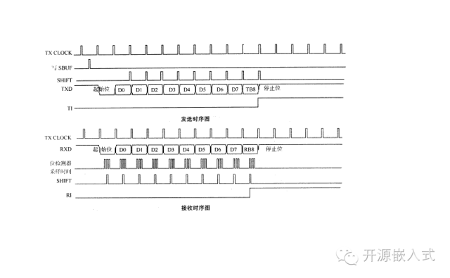
RS232 read/write timing diagram:
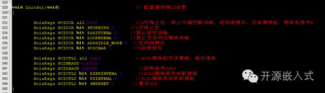
Below are some programming examples. Since there are many RS232 programming experiences using the 51 microcontroller, I will share a communication example written with DSP. Due to the large size of the library and header files, I will only share the communication part of the program. If you need the complete project, you can send a message to our official account. We will respond as soon as possible and send it to your email.
Program brief description: Development environment CCS4.2, chip TMS320F2812, mode: interrupt mode read/write
Using module: SCIA module
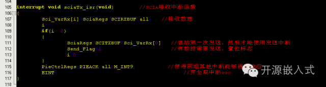
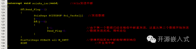
The communication between DSP serial ports and microcontroller serial ports has significant differences, but the basic communication process is the same. First, configure the GPIO (configuration is needed due to multiple modes, which ordinary microcontrollers do not require). After configuration, set the communication parameters. Once the parameters are set, interrupts can be used to send and receive. (Sending can also be done without interrupts; I just wrote a process, but in practical use, it should be written according to functionality. The sending I wrote continuously sends data), below is the program.

If you need technical support, please add our official group for consultation!
Our official QQ group 1: 281549832
Special thanks to the strong support from netizens.
Our open-source team is constantly expanding, and we hope everyone will join us soon.
Once again, thank you all for your strong support!

Everyone, please follow us!