The Secrets of PCB Design: Why Differential Signal Lines Must Be “Precisely Equal Length”?

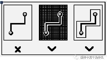
A clear and in-depth analysis of the core rules in high-speed circuit design In high-speed PCB design, differential signal technology has become a key means to enhance signal quality. From commonly used USB interfaces and HDMI high-definition transmission to complex network communication devices, the application of differential signals is ubiquitous. However, one question often troubles … Read more


Understanding the Physical Layer Implementation of the CAN Protocol

Understanding the Physical Layer Implementation of the CAN Protocol

A comprehensive analysis of the CAN bus physical layer based on ISO11898 and ISO11519 1 CAN Hardware Control Layer CAN communication[1] is an asynchronous communication method, differing from synchronous communication methods like I2C and SPI that rely on clock signals. CAN communicates through a pair of differential signal lines, <span>CAN_H</span> and <span>CAN_L</span>, using differential signals … Read more

Key Considerations in FPGA Design

Key Considerations in FPGA Design

Whether you are a logic designer, hardware engineer, or system engineer, or even hold all these titles, if you are using FPGAs in any high-speed and multi-protocol complex system, you are likely to face challenges related to device configuration, power management, IP integration, signal integrity, and other critical design issues. However, you do not have … Read more

Considerations for MIPI Signal PCB Design

Considerations for MIPI Signal PCB Design

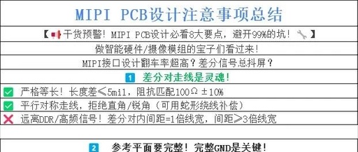
MIPI (Mobile Industry Processor Interface) is a core transmission standard for devices such as smartphones, tablets, and automotive systems, which includesD-PHY (used for CSI cameras/DSI displays) andC-PHY (higher bandwidth, no independent clock) physical layer protocols. Its characteristics include: Differential Signals: D-PHY includes 1 pair of clock + 1~4 pairs of data lines; C-PHY transmits embedded … Read more

Understanding PROFIBUS DP DB9 Interface Signals and Design

Understanding PROFIBUS DP DB9 Interface Signals and Design

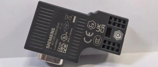
PROFIBUS DP Basic Introduction PROFIBUS DP is a classic fieldbus protocol introduced by Siemens many years ago, widely used in various industrial applications. With more domestic manufacturers participating in the production and manufacturing of PROFIBUS DP related devices, various designs for the physical connection of PROFIBUS DP have emerged. To facilitate everyone in designing the … Read more

PCB Layout and Routing Guidelines

PCB Layout and Routing Guidelines

1. Layout 10 Rules for Component Layout: 1. Follow the principle of “large first, small later; difficult first, easy later,” meaning that important circuit units and core components should be prioritized in layout. 2. The layout should refer to the schematic diagram, arranging major components according to the main signal flow direction of the board. … Read more

PCB Design Checklist: Routing

PCB Design Checklist: Routing

Route according to the 50-ohm impedance line width, try to route from the center of the pad, keeping the lines straight and preferably on the top layer. When a bend is necessary, make it at a 45-degree angle or as an arc, preferably bending near capacitors or resistors. If routing meets the matching requirements of … Read more