1. Hardware Selection
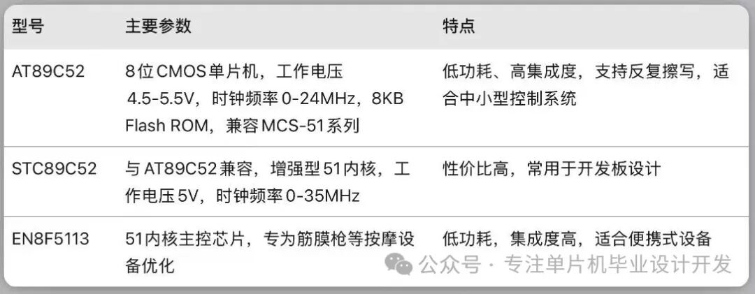
1. Core Controller
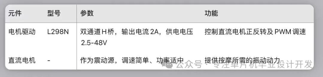
2. Driver Module
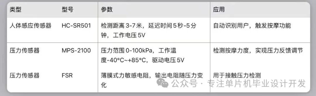
3. Sensor
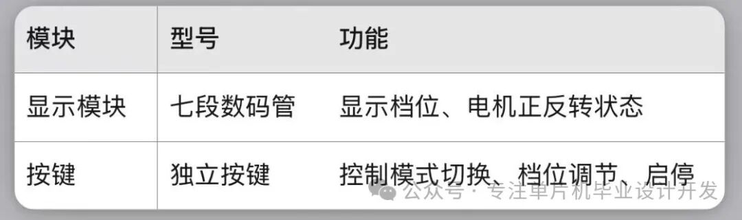
4. Display and Interaction Module
2. Software Architecture Design and Control Algorithm
1. Software Architecture
● Main program flow: Initialization (I/O ports, timers, interrupts) → Sensor data acquisition → Key scanning → PWM waveform generation → Motor drive → Status display.
● Modular design: Divided into sensor driver module, PWM control module, display module, key processing module, improving code reusability and maintainability.
● Development environment: Keil C51 compiler, Proteus simulation environment.
2. Control Algorithm Principles
● PWM speed control algorithm: By changing the duty cycle of the PWM wave generated by the timer interrupt (e.g., a duty cycle of 50% corresponds to medium speed), control the average voltage of the DC motor armature, achieving smooth speed adjustment and thus adjusting the massage intensity.
● Sensor fusion logic: The human infrared sensor activates the system upon detecting a user, while the pressure sensor continuously monitors the massage intensity, providing feedback to adjust the PWM duty cycle for adaptive intensity control.
● Timing control: The timer is used to set the massage duration (e.g., 5-15 minutes), automatically stopping after the time limit.
3. Source Code Example (Key Modules)
(1) PWM Motor Control Code
#include <reg52.h><br />#include <stdio.h><br />sbit ENA = P2^0; // L298N enable pin<br />sbit IN1 = P2^1; // Motor forward control<br />sbit IN2 = P2^2; // Motor reverse control<br />unsigned int PWM_Duty = 50; // Initial duty cycle 50%<br />unsigned int count = 0; // Interrupt counter<br />// Timer 0 initialization (1ms interrupt)<br />void Timer0_Init() {<br /> TMOD = 0x01; // Mode 1: 16-bit timer<br /> TH0 = 0xFC; // Initial value setting (1ms@12MHz)<br /> TL0 = 0x18;<br /> ET0 = 1; // Enable timer interrupt<br /> EA = 1; // Enable global interrupt<br /> TR0 = 1; // Start timer<br />}<br />// Timer 0 interrupt service function (generate PWM)<br />void Timer0_ISR() interrupt 1 {<br /> TH0 = 0xFC; // Reload initial value<br /> TL0 = 0x18;<br /> count++;<br /> if (count <= PWM_Duty) {<br /> ENA = 1; // High level duration (duty cycle)<br /> }<br /> else {<br /> ENA = 0; // Low level duration<br /> }<br /> if (count >= 100) {<br /> count = 0; // Cycle 100ms (frequency 10Hz)<br /> }<br />}<br />// Motor forward<br />void Motor_Forward() {<br /> IN1 = 1;<br /> IN2 = 0;<br />}<br />// Motor reverse<br />void Motor_Backward() {<br /> IN1 = 0;<br /> IN2 = 1;<br />}<br />void main() {<br /> Timer0_Init();<br /> Motor_Forward(); // Default forward<br /> while(1) {<br /> // Adjust PWM_Duty to change speed via keys<br /> // Example: PWM_Duty = 30; // 30% duty cycle (low speed)<br /> // PWM_Duty = 70; // 70% duty cycle (high speed)<br /> }<br />}(2) HC-SR501 Human Motion Sensor Code
sbit PIR_Sensor = P3^3; // Sensor output connected to P3.3<br />sbit Motor_Control = P2^0; // Motor control pin<br />void delay_ms(unsigned int ms) {<br /> unsigned int i, j;<br /> for(i = ms; i > 0; i--)<br /> for(j = 112; j > 0; j--);<br />}<br />void main() {<br /> Motor_Control = 0; // Initial motor stop<br /> while(1) {<br /> delay_ms(50);<br /> if (PIR_Sensor == 1) { // Person detected<br /> Motor_Control = 1; // Start motor<br /> }<br /> else {<br /> Motor_Control = 0; // Stop motor<br /> }<br /> }<br />}3. Overall System Design
1. Hardware Architecture
● Core Module: Microcontroller control module (AT89C52/STC89C52), power module (providing 5V and drive voltage), motor driver module (L298N + DC motor).
● Auxiliary Module: Sensor module (human detection + pressure sensing), display module (seven-segment display), key input module.
2. Workflow
1. When the user approaches, the HC-SR501 detects the human body, and the system starts.
2. The user selects the massage mode (e.g., gentle, standard, strong) and level via keys.
3. The microcontroller generates PWM signals through the timer, driving the motor to vibrate via L298N.
4. The MPS-2100/FSR sensor continuously detects the massage intensity, providing feedback to adjust the PWM duty cycle.
5. The seven-segment display shows the current level and working status, automatically stopping after the timer ends.
If you have any questions, please message me privately, thank you 🙏❤️