Click on the above“Wenting Says Follow me!
Recently, due to project requirements, I needed to interface with a laser device that communicates via the RS232 serial port. Although I have a background in computer science, I had only heard of serial ports before and didn’t know how to work with them. This was a great opportunity for me to learn.
Let me first explain how I approached this.
The manufacturer provided an RS232 serial port integration document. I read through the content several times to understand the basics, and then I started writing the integration code. To be honest, with AI being so powerful nowadays, it felt a bit wrong not to use it, so I leveraged ChatGPT to help me write the code. It quickly generated the following seven functions for me.
1. Public API: Connect(), Disconnect().
2. Frame Build & Parse: SendFrame(), BuildFrame(), ReadFrame();
3. CRC16 (MODBUS) fast lookup table calculation functions: CrcTable(), CRC16().
Great, the efficiency was impressive, and I was quite pleased as it solved many of my problems. However, when I was excitedly testing the code it generated, I found that no matter how I sent messages, the laser device did not respond. I was connected to the serial port, so why was there no message returned? I couldn’t help but wonder, so I asked the AI to help me analyze the possible reasons.
1. Your CRC is incorrect (currently the most likely reason).
2. The serial port connection is not properly established.
3. RTS/DTR signals are causing the laser to not respond.
4. Certain signals need to be shorted (depending on the USB-RS232 adapter).
5. Serial port number mismatch / the laser is not enabled for RS232.
First, I could rule out 2/4/5 because the laser has its own host computer, and the host program showed that it could receive information from the laser. Next, I needed to rule out 3, which was relatively easy to set up with just two lines of code:
_port.RtsEnable = false;
_port.DtrEnable = false;
After running the program again, it still didn’t work, so I suspected 1, which the AI also indicated was the most likely issue. I needed to verify the CRC.
CRC Verification
CRC Verification, full name Cyclic Redundancy Check, is a method for generating a short checksum based on data such as network packets or computer files.
-
Purpose: Used for detecting whether the original data has been corrupted during transmission or storage.
-
Characteristics: Simple calculation, strong error detection capability, especially effective in detecting burst errors. It is widely used in network communication (e.g., Ethernet), data storage (e.g., ZIP, RAR compressed files), and other fields.
Common standard polynomials include:
-
CRC-8: Used for some simple applications.
-
CRC-16: Used in Modbus, USB, and other protocols.
-
CRC-32: Used in Ethernet (IEEE 802.3), ZIP, RAR, PNG, etc., and is very widely applied.
Modulo 2 Operations
In CRC calculations, addition, subtraction, multiplication, and division are all modulo 2 operations, which is essentially XOR operations.
-
Addition:
<span>0+0=0</span>,<span>0+1=1</span>,<span>1+0=1</span>,<span>1+1=0</span>(no carry) -
Subtraction: Same rules as addition.
-
Multiplication and Division: Based on modulo 2 addition and subtraction.
Having clarified the concept, I asked the AI to calculate it, and I also used a calculator to verify, and the results matched, indicating that the CRC calculation was correct. So where was the problem? I had to calm down and think again.
I carefully re-read the integration document, and when I saw the following line, I had a thought.

Since the default address is 1, could it be that someone changed the default address? I asked the project party personnel, but they didn’t know. I then asked them to help me log into the host program to look for clues, and I finally found a field that looked very much like the laser device’s address.
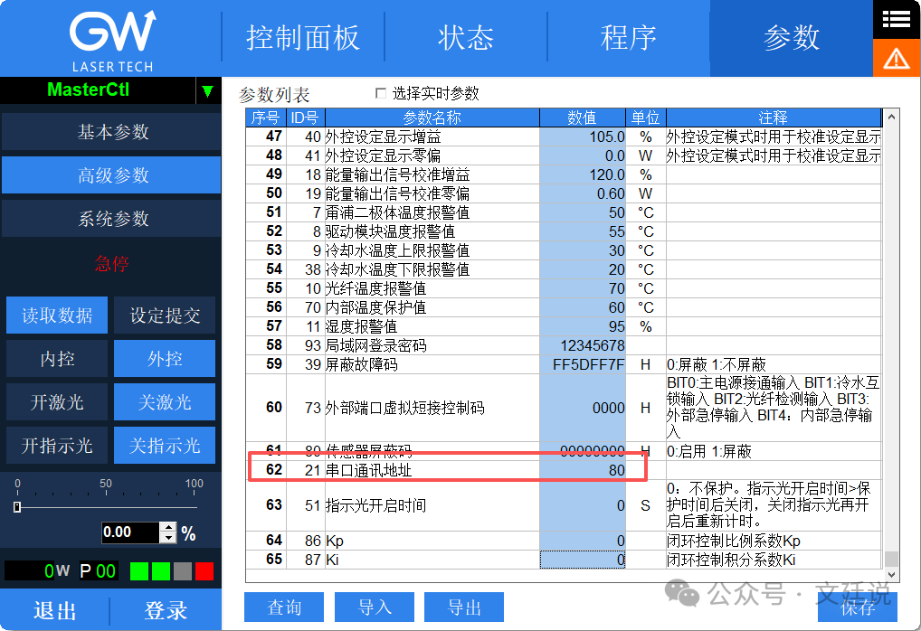
I also discovered the data frame sent by the host program
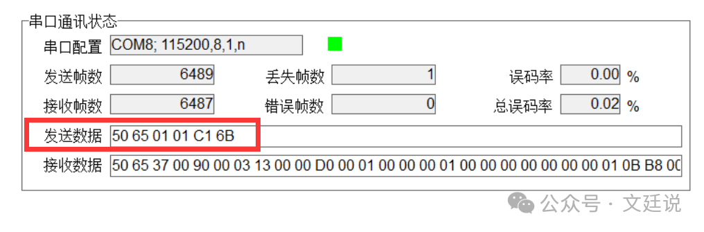
The starting bit 50 is just 80 in hexadecimal, so I could confirm that. I then changed the laser device’s address and sent the message again, but still received nothing. This was puzzling. I suddenly remembered that I had previously used a serial port debugging assistant, so I decided to try it out. It automatically generates the CRC checksum field, and after testing, I finally received a message. My excitement at that moment was indescribable, but I had to stay calm and analyze why my program wasn’t receiving the sent messages. Upon inspection, I found that the issue lay in the high and low byte order of the CRC check. The document stated that the high byte comes first and the low byte comes second, which was actually unnecessary. So, I swapped their positions, and finally, my program received the information from the laser device. At last, I successfully established communication between my software and the laser device, and I could finally relax after this tense period.
Reflection and Summary
What is RS232?
RS-232, full name Recommended Standard 232, is a standard for serial communication established by the Electronic Industries Alliance.
-
Essence: A standard that defines the communication interface between data terminal equipment and data communication equipment, specifying electrical characteristics, connector shapes, signal functions, etc.
-
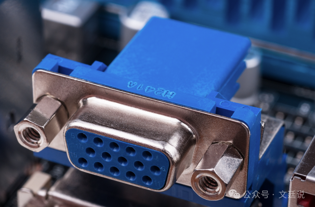
Most common form: What we usually refer to as the “serial port” or COM port. On personal computers, it typically appears with a 9-pin D-Sub connector.
-
Key Features: Point-to-point, full-duplex, asynchronous communication, using positive and negative voltages to represent signals: +3V ~ +15V = logic 0, -3V ~ -15V = logic 1
-
Where is it now? Mainly found in industrial control, equipment debugging, and professional instruments that require stable, simple, long-distance communication.
-
Why has it been replaced? In the consumer field, it has been replaced by more advanced and faster interfaces like USB due to its slow speed, lack of hot-swapping, and complex configuration.
In this project, the laser device protocol = RS232 transmission + custom frame format + CRC-16/Modbus check. It is not the Modbus protocol, but simply uses the Modbus CRC algorithm.
Return Data Frame Parsing
The return frame format for ID113:
Address(1) + Command(1) + Data Length(1) + Sequence Number(1) + Data(8) + CRC(2)
Return frame data content:
1) Raw frame (Index → Decimal / Hexadecimal)
0: 80 (0x50) // Address1: 113 (0x71) // RequestNo2: 9 (0x09) // Data Length3: 1 (0x01) // Sequence4: 144 (0x90) // data[0]5: 0 (0x00) // data[1]6: 3 (0x03) // data[2]7: 19 (0x13) // data[3]8: 0 (0x00) // data[4]9: 0 (0x00) // data[5]10:208 (0xD0) // data[6]11:0 (0x00) // data[7]12:6 (0x06) // CRC low13:28 (0x1C) // CRC high2) data(8) (in order)
data = [0x90, 0x00, 0x03, 0x13, 0x00, 0x00, 0xD0, 0x00]According to the protocol, the first 4 bytes are MachineStatus (overall machine status, 4 bytes, little-endian), and the last 4 bytes are FaultStatus (fault, 4 bytes, little-endian)
3) Calculate MachineStatus / FaultStatus (little-endian)
MachineStatus = 0x13 <<24 | 0x03<<16 | 0x00<<8 | 0x90= `0x13030090`FaultStatus = 0x00 <<24 | 0xD0<<16 | 0x00<<8 | 0x00= `0x00D00000`4) How to convert MachineStatus to bits (bit0, bit1…)
uint machine = BitConverter.ToUInt32(rsp2, 4);int bitN = (int)((machine >> N) & 1u);bool bitN_bool = ((machine >> N) & 1u) == 1;5) Specifically for this frame: The low 8 bits of MachineStatus = 0x13030090 (byte0 = 0x90)
`0x90` in binary is: `1001 0000` (from high to low) according to bit numbering (bit7..bit0): bit7 bit6 bit5 bit4 bit3 bit2 bit1 bit0 1 0 0 1 0 0 0 0 so:* bit0 = 0* bit1 = 0* bit4 = 1* bit7 = 16) Conclusion
The protocol defines "Power On Control" (Bit0) as false (0) and "Main Power On / System Ready" (Bit1) as false (0)
 Long press to follow and you will find that maintaining a childlike heart is something to be proud of