
This article will detail the Modbus communication configuration process between the S7-1200 PLC and the V20 inverter.

1. Required: One S7-1200 PLC with an RS485 communication module and one V20 inverter.
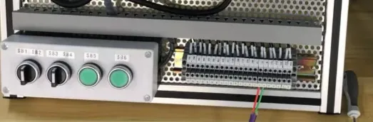
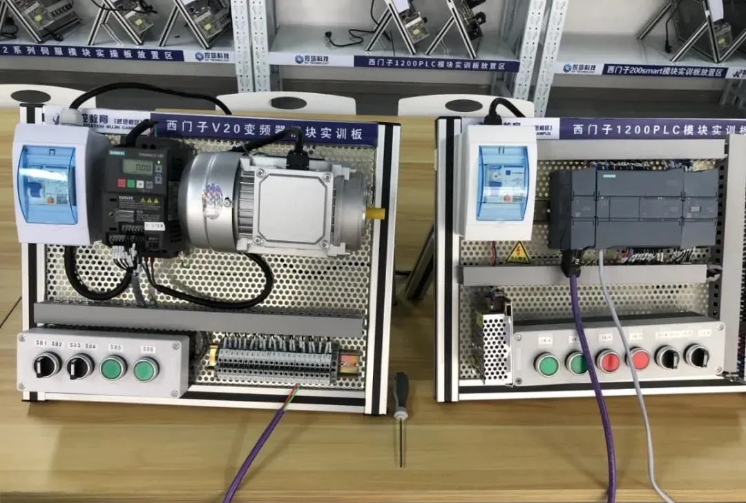 2. Wiring method for the RS485 module and the V20 inverter: Connect the red wire to the P+ terminal and the green wire to the N- terminal.
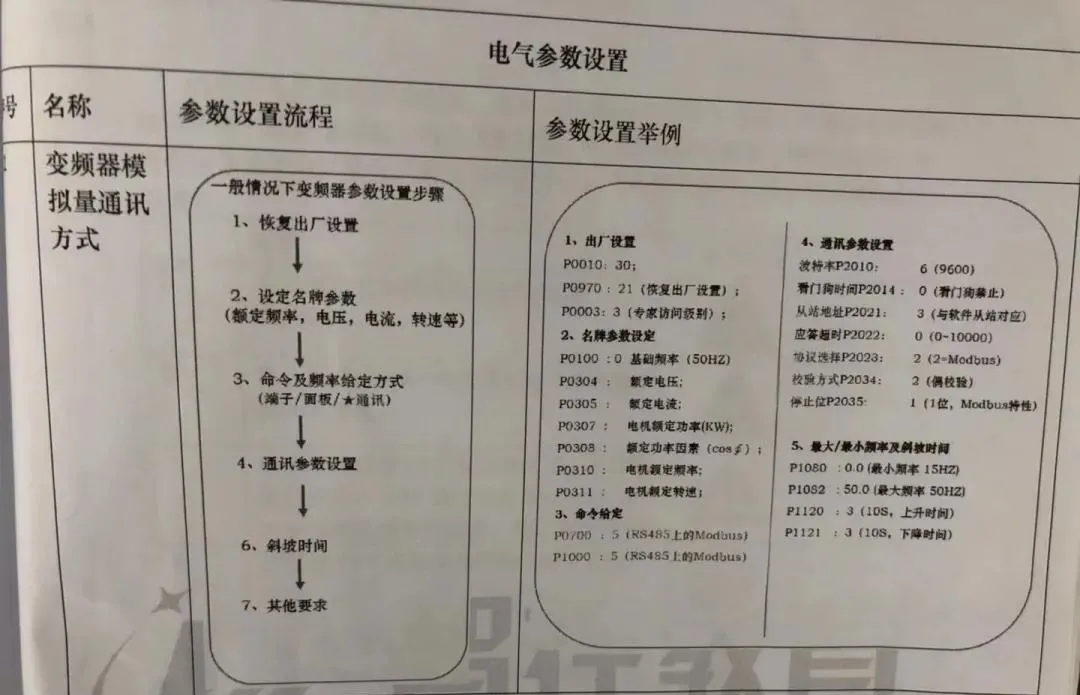
 3. Configure parameters for the V20 inverter.
 4. Create a new project in the TIA Portal software and upload the hardware configuration of the S7-1200 PLC.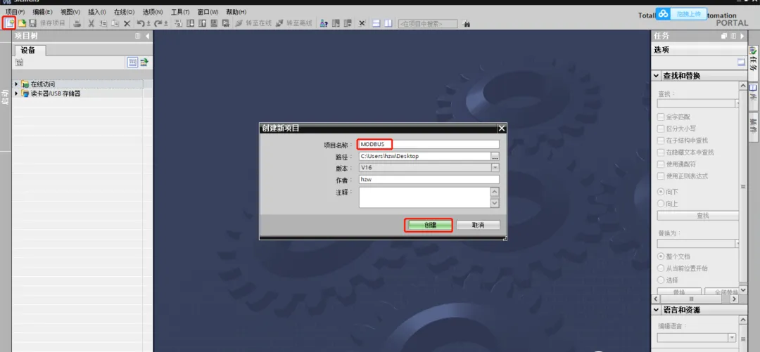
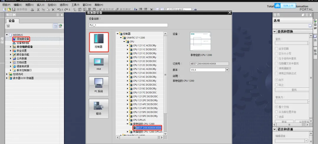
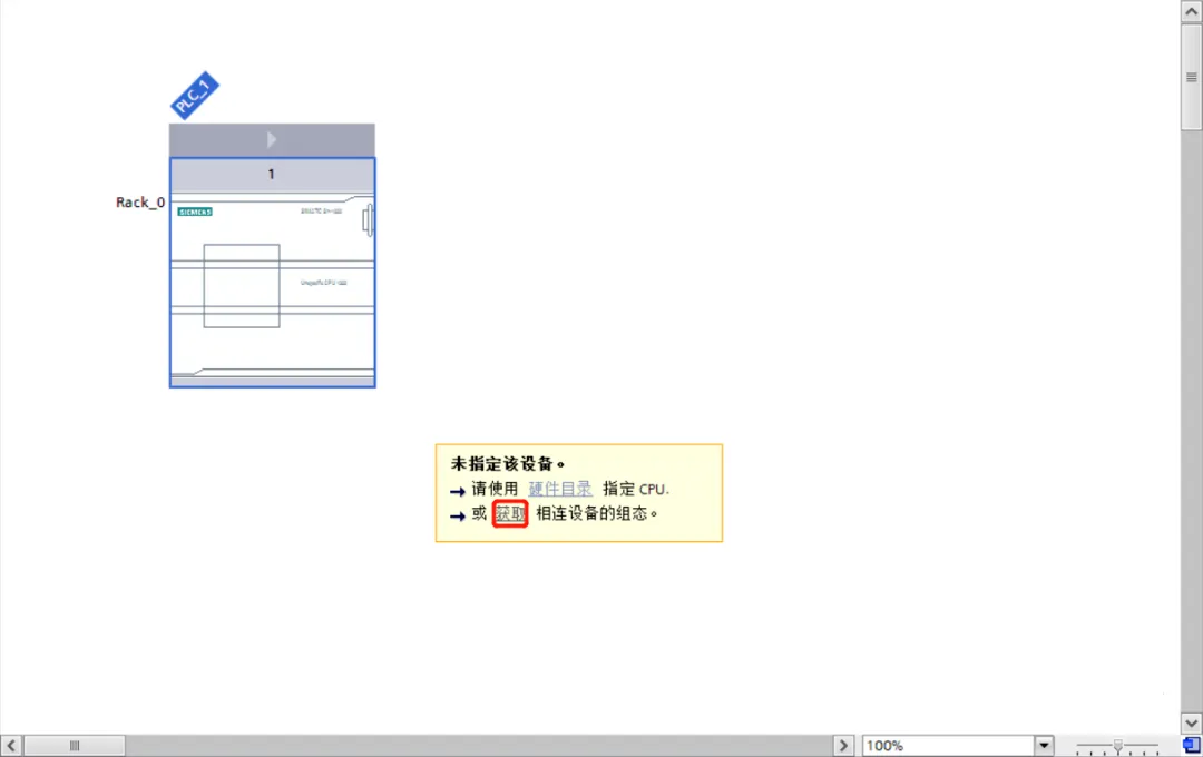
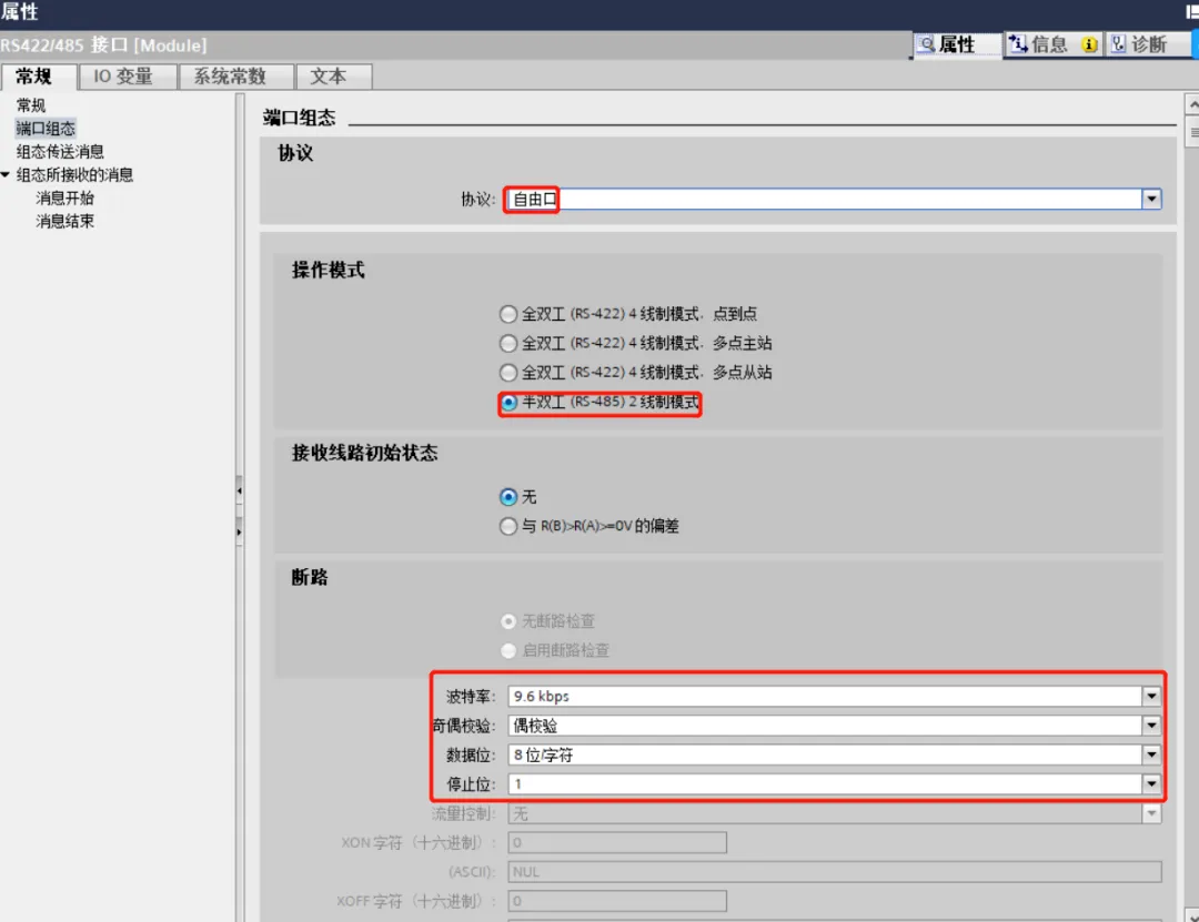
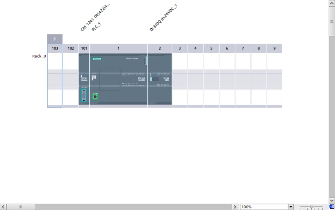 5. Configure the RS485 module communication parameters to match those of the V20 inverter, specifically: baud rate 9600 bps, 8 data bits, even parity.
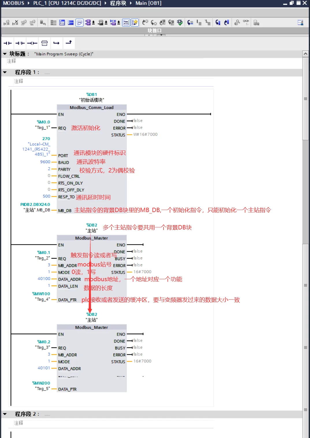
 6. Add Modbus communication instruction blocks in the program.
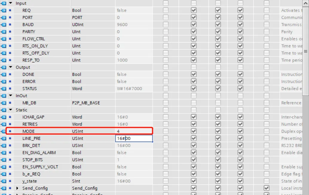
 7. Change the mode parameter value in the initialization data block (DB) to 4.
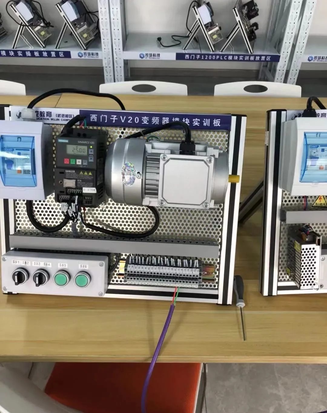
 8. The program test results show that the motor can start and stop normally, with the key Modbus address function definitions as follows:Control Command (40100):047E (Stop), 047F (Forward), 0C7F (Reverse)Frequency Setting (40100):16#0-16#4000 corresponds to 0Hz-50Hz analog output.
 9. The connection status can be determined by observing the communication indicator lights on the RS485 module: when the TX (transmit) and RX (receive) indicator lights flash alternately, it indicates that Modbus communication has been successfully established.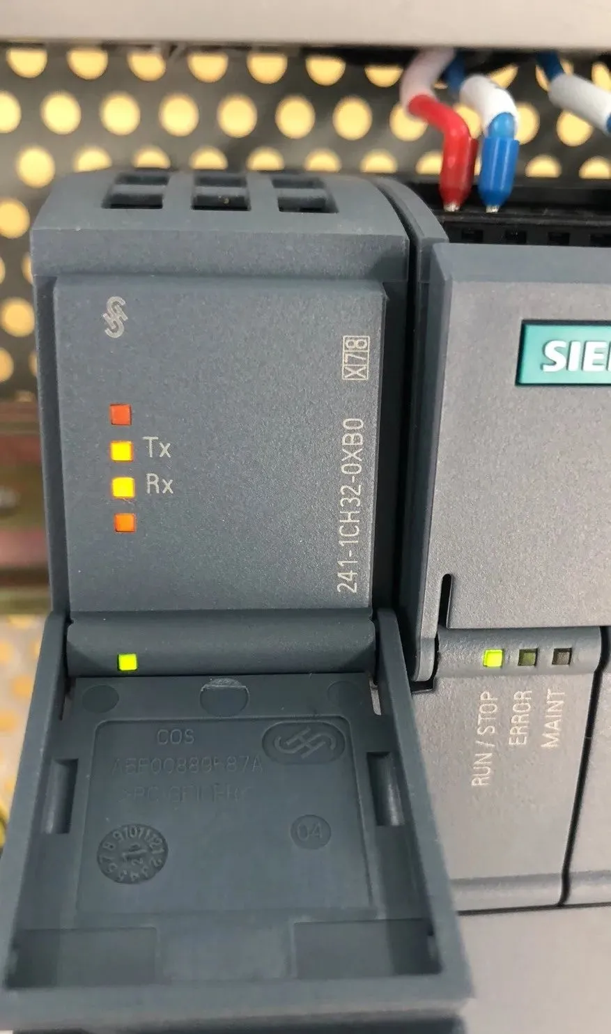
Through the Modbus communication implementation between the S7-1200 PLC and the V20 inverter, we not only grasped the essence of industrial bus configuration but also appreciated the core value of “parameter consistency” and “step-by-step verification” in automation debugging. From the standardized operation of hardware wiring to the precise matching of software parameters, each step is a cornerstone for ensuring stable system operation.
As Industry 4.0 continues to advance, traditional communication protocols like Modbus will still play an important role at the device level, and the engineer’s mastery of fundamental principles and accumulation of practical experience are the foundation for tackling complex industrial scenarios. In the future, we look forward to exploring more interconnectivity between cross-brand devices to provide more flexible solutions for the implementation of smart manufacturing.
Previous Recommendations
Master this diagram to solve 80% of inverter hardware faults
Application and programming of PLC communication MODBUS protocol, start with this article!
How to achieve positioning function of encoders controlled by PLC?
Have you encountered the “pits” of using timers in S7-1200?
Mitsubishi PLC using BD board to control two inverters in polling case
How to read and write local real time in S7-1200 PLC
Bookmark this, essential knowledge summary for automation PLC!
Siemens S7-1200 and S7 communication, after reading this article, communication won’t seem so difficult!
Why install encoders on motors? How do encoders work?
PROFINET communication between S7-200SMART series PLCs
Communication guide between Weintek touch screen and Mitsubishi PLC
Custom data types (UDT) in TIA Portal, you must master!
Application and programming of PLC communication MODBUS protocol, start with this article!