In the field of industrial automation, equipment manufacturers (OEMs) often provide their proprietary communication protocols, such as Profinet, CIP, DeviceNet, and ControlNet, to facilitate communication between workshop devices. With the presence of controllers, instruments, and peripheral devices from different manufacturers, a question arises: how can data exchange be achieved among them? To address this challenge, open protocols have emerged, which fill the gaps of proprietary protocols in connecting third-party devices. Common standard open protocols include Modbus, OPC DA, OPC UA, and MQTT. This article will delve into the Modbus protocol, including its advantages, types, and implementation methods.
What is Modbus
Modbus is a communication protocol developed by Modicon (now Schneider Electric) in 1979, initially used for programmable logic controllers (PLCs). Modbus can transmit data over serial lines or Ethernet. Due to its openness and universality, an increasing number of devices support the Modbus protocol, making it a widely accepted communication method.
In practical applications, data acquisition and monitoring systems (SCADA) extensively use the Modbus protocol to obtain data from remote terminal units (RTUs) and PLCs.
Types of Modbus Communication
The Modbus protocol can be roughly divided into three categories:
- 1. Modbus RTU
- 2. Modbus ASCII
- 3. Modbus TCP
1. Modbus RTU
Modbus RTU is the most commonly used Modbus protocol. It is a simple serial communication protocol that can be transmitted using standard UART technology.
- • Baud Rate Range: 1200 bps to 115200 bps; most devices only support 38400 bps.
- • Data Format: Transmitted bit by bit in 8-bit bytes.
- • Communication Structure: Master-slave mode. A Modbus master can connect to a maximum of 254 slaves.
- • Address Allocation: Each slave has a unique 8-bit device address (also known as unit number). The master specifies the target slave address in the message, and only the slave with a matching address will respond; otherwise, the master will determine it as a “no response” error.
- • Slave Definition: Any peripheral device that uses Modbus to analyze data and respond to the master, such as I/O transmitters, valves, network drives, or measuring instruments.
- • Physical Medium: Serial communication, commonly used standards include RS232, RS422, RS485.
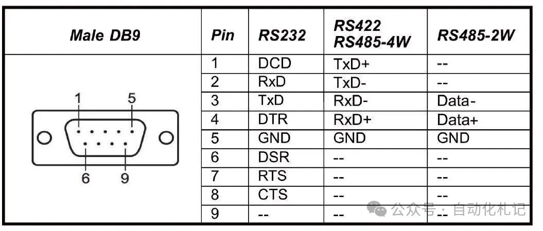 Figure 1 – Modbus Protocol | Physical connection methods using DB9 interface for RS232, RS485, RS422
2. Modbus ASCII
Modbus ASCII is an earlier version of the Modbus protocol that retains all elements of the RTU message but represents data entirely in readable ASCII characters. Currently, Modbus ASCII is no longer widely supported and is not included in the official Modbus protocol specification.
3. Modbus TCP
With the popularity of Ethernet, Ethernet TCP/IP has become the most common network protocol. Modbus TCP encapsulates Modbus RTU packets within TCP messages, allowing it to be transmitted over standard Ethernet.
- • Addressing Method: Unlike RTU, which uses slave addresses, Modbus TCP primarily relies on the device’s IP address (e.g., 192.168.0.20).
- • Port Number: Defaults to 502 (can be reconfigured).
- • Communication Model: Follows the OSI network model.
- • Role Transition: Transitions from the traditional master-slave relationship to a client-server relationship, where the master acts as the client and the slave as the server.
- • Concurrency: Supports multiple clients communicating with multiple servers simultaneously, thanks to the peer-to-peer nature of Ethernet.
- • Physical Medium: Commonly uses RJ45 LAN cables to connect Modbus TCP devices.
Modbus Message Structure
To fully utilize the Modbus protocol, it is essential to understand its working mechanism. Modbus uses registers to store and transmit different types of data. Registers can be understood as “data buckets” that hold data points. The main types of registers are as follows:
- • Discrete Inputs (contacts)
- • A single bit register (Bit) that only supports read operations.
- • Similar to contact inputs in PLC programming.
- • Coils
- • A single bit register used for output.
- • Supports read and write operations.
- • Input Registers
- • 16-bit registers used only for input.
- • Read-only.
- • Holding Registers
- • 16-bit registers that support read and write.
- • The most versatile function, can be used for input, output, and storing any data.
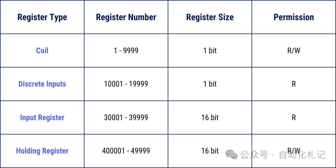 Figure 2 – Modbus Protocol | Message Structure
Modbus Function Codes
The Modbus protocol defines a series of Function Codes used to access different types of registers.
Since Modbus defines four types of data blocks, and the addresses (or register numbers) of these data blocks may overlap, it is necessary to specify both the address (register number) + function code to accurately locate the data.
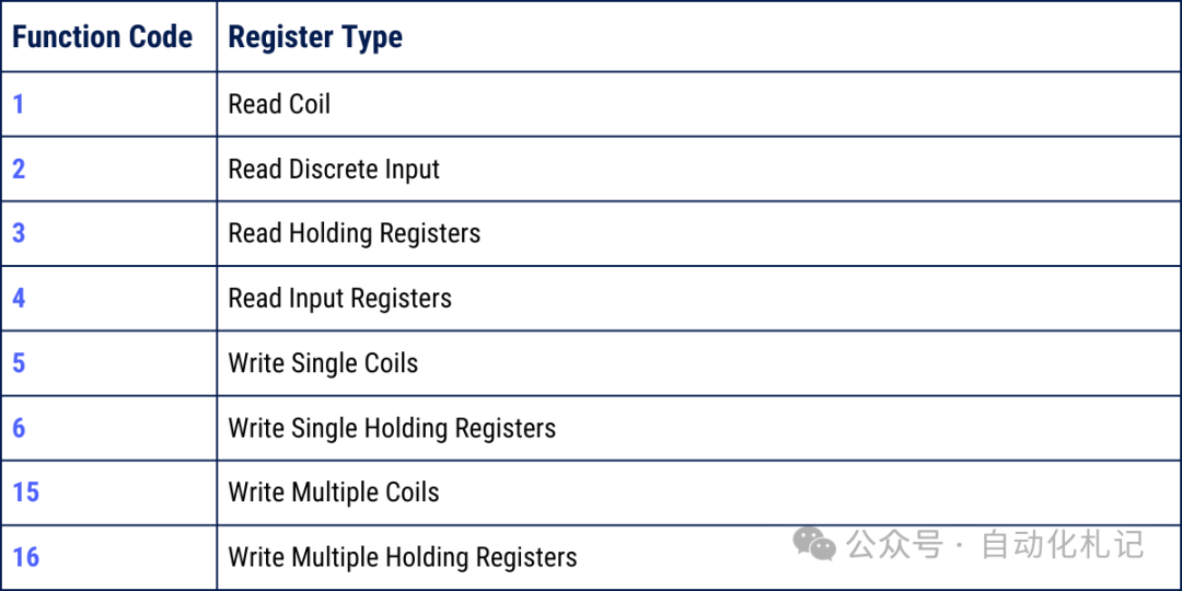 Figure 3 – Modbus Protocol | Function Code List
(Note: The function codes listed in the chart are not exhaustive but cover the most commonly used and important parts; focus on mastering these when learning and using. A complete list can be found in the appendix at the end.)
Modbus Error (Exception) Codes
When a slave detects a request message but finds it contains an error, it will not return normal data but will return an Exception Response.
The exception response message includes:
- • Slave address (unit number);
- • Function code copy (highest bit set to 1 to indicate an exception);
- • Exception code.
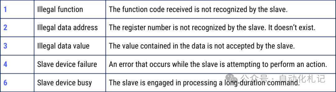 Figure 4 – Modbus Protocol | Exception Code Description (Complete list can be found in the appendix at the end)
Conclusion
This article provides a basic introduction to the Modbus protocol. There are numerous resources online that delve into its specific implementation and applications, and readers are encouraged to further study and explore.
As a flexible and universal industrial network protocol, Modbus has been widely used in the automation field. Therefore, it is essential for industrial control and automation engineers to deeply understand and master the Modbus protocol.
Appendix: Function Codes and Exception Codes table, as well as a comparison table of Modbus register types and address ranges
📑 Modbus Function Code Table (Commonly Used)
| Function Code (Decimal) | Function Code (Hexadecimal) | Function Description | Applicable Register Type | Read/Write Attribute |
|---|---|---|---|---|
| 1 | 0x01 | Read Coil Status | Coils | Read Only |
| 2 | 0x02 | Read Discrete Input Status | Discrete Inputs | Read Only |
| 3 | 0x03 | Read Holding Registers | Holding Registers | Read Only |
| 4 | 0x04 | Read Input Registers | Input Registers | Read Only |
| 5 | 0x05 | Write Single Coil | Coils | Write |
| 6 | 0x06 | Write Single Register | Holding Registers | Write |
| 15 | 0x0F | Write Multiple Coils | Coils | Write |
| 16 | 0x10 | Write Multiple Registers | Holding Registers | Write |
Note: There are more extended function codes (such as diagnostics, file logging, etc.), but the above table is the most commonly used and basic set.
⚠️ Modbus Exception Code Table
| Exception Code (Decimal) | Exception Code (Hexadecimal) | Name | Description |
|---|---|---|---|
| 1 | 0x01 | Illegal Function | The function code received by the slave is invalid or not supported. |
| 2 | 0x02 | Illegal Data Address | The requested data address is out of the slave’s available range. |
| 3 | 0x03 | Illegal Data Value | The requested value is out of the allowed range or format error. |
| 4 | 0x04 | Slave Device Failure | The slave encountered an unrecoverable error while processing the request. |
| 5 | 0x05 | Acknowledge | The slave has accepted the request, but processing will take a long time; the client should query later. |
| 6 | 0x06 | Slave Device Busy | The slave is busy processing another request and cannot respond at this time. |
| 7 | 0x07 | Negative Acknowledge | The slave refuses to execute the request. |
| 8 | 0x08 | Memory Parity Error | The slave detected a memory parity error. |
| 10 | 0x0A | Gateway Path Unavailable | The gateway detected that the target path is unreachable. |
| 11 | 0x0B | Gateway Target Device Failed to Respond | The gateway did not receive a response from the target device. |
When writing PLC programs, configuring SCADA, or debugging communication, it is very practical to quickly look up the corresponding function codes and exception codes.
Modbus Register Types and Address Range Comparison Table
| Data Type | Register Range (Logical Address) | Common Representation | Read/Write Attribute | Description |
|---|---|---|---|---|
| Coils | 00001 – 09999 | 0xxxx | Read/Write | Single bit (1bit), represents digital output, can be written (on/off). |
| Discrete Inputs | 10001 – 19999 | 1xxxx | Read Only | Single bit (1bit), represents digital input, read-only. |
| Input Registers | 30001 – 39999 | 3xxxx | Read Only | 16-bit registers, commonly used for analog input, read-only. |
| Holding Registers | 40001 – 49999 | 4xxxx | Read/Write | 16-bit registers, most versatile, can store input, output, and any data. |
🔎 Note:
- 1. The logical addresses (e.g., 40001) in the above table are merely conventional representations in the industry; in reality, Modbus messages transmit “offsets”, not complete addresses.
- • For example: Logical address 40001 → Register address offset in the message is 0.
- • Logical address 40010 → Register address offset in the message is 9.
- • Function code 01 (Read Coils) → Corresponds to 0xxxx area.
- • Function code 03 (Read Holding Registers) → Corresponds to 4xxxx area.
Follow Automation Notes for insights focused on industrial automation and PLC sharing.