 Search on WeChat
 Technical Training1. Task Control Requirements Description
Use FX5U to achieve Modbus RTU communication with Mitsubishi E700 inverter, with functions: change frequency, forward, reverse, stop. As shown in Figure 1-1.
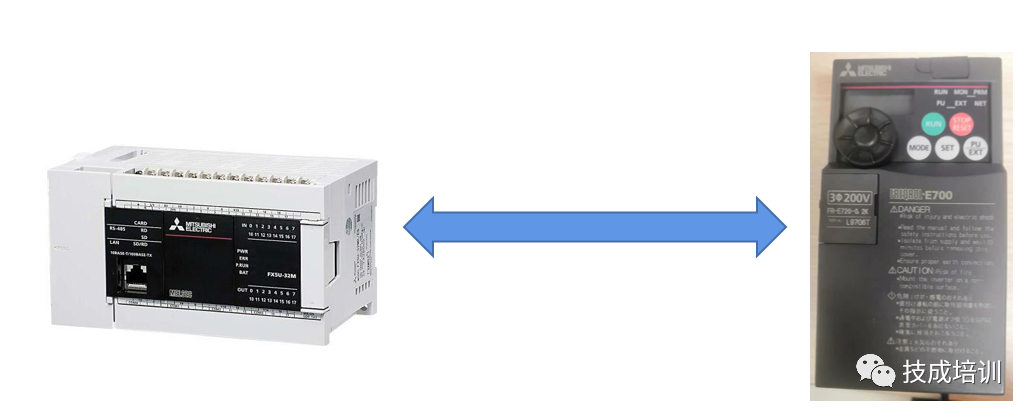
Figure 1-1 FX5U and Mitsubishi Inverter E700
2. Related Basic Knowledge
The case in this task is based on the application of Mitsubishi FX5U series PLC. Please self-assess if you have the following basics before learning this case. If you are not familiar with the related basic knowledge, please follow the links provided below for preliminary learning.
1. Understanding of communication?
Course viewing link: https://course.jcpeixun.com/6015/458679.html
2. What is serial communication?
Course viewing link: https://course.jcpeixun.com/6015/458681.html
3. Differences between RS232, RS485, and RS422?
Course viewing link: https://course.jcpeixun.com/6015/458748.html
4. What does the communication format include?
Course viewing link: https://course.jcpeixun.com/6015/458749.html
5. What is a communication protocol?
Course viewing link: https://course.jcpeixun.com/6015/458786.html
6. Understanding of RS2 instruction?
Course viewing link: https://course.jcpeixun.com/7012/461003.html
01Hardware Interface
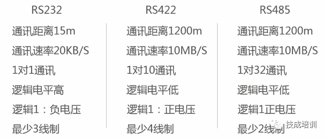
The communication interface standard is the hardware protocol for communication, providing mechanical, electrical, and functional characteristics and regulations. It also defines the connection methods for transmission media and network interfaces, as well as the methods for data sending and receiving. Among serial data interface standards, the most commonly used are RS232, RS422, and RS485 serial interface standards. This case uses the RS485 interface.
02Communication Protocol
The communication protocol mainly looks at the communication format and data format.
(1) Communication Format
In serial asynchronous communication, both parties must uniformly set the method of data transmission, the length of the data being transmitted, the method of verification, and the transmission rate to ensure correct communication between both parties. These parameters that are uniformly set by both parties are called the communication format.
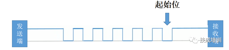
The sender defaults to a logical 1 state.
Before sending data, a logical 0 is first sent to notify the other party to start receiving data.
Start bit: Used to notify the other party to start receiving data.

Data bits: The actual useful information.
Data bits can be 7 or 8 bits, set according to actual needs.
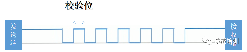
Data bits: Verify whether the data bits are sent correctly.
Can set odd parity, even parity, or no parity.
|
Setting |
Number of data bits set to 1 |
Parity bit |
|
Odd parity |
Odd |
0 |
|
Even |
1 |
|
|
Even parity |
Odd |
1 |
|
Even |
0 |
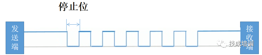
Stop bit: Marks the end of a character’s transmission, usually the stop bit is a high level.Can set 1 bit or 2 bits. Both parties must be consistent.
(2) Data Format
This case takes Modbus RTU communication as an example.
Modbus RTU communication format:
1 start bit
8 data bits
1 parity bit, none if no parity
1 stop bit (with parity), 2 stop bits (without parity)
Modbus RTU data format

One code corresponds to a set of communication formats.
For example: Address code: 01H, 1 start bit, 8 data bits, odd parity, 1 stop bit, so the address code
0 00000001 0 1
Start bit: 1
Data bit: 00000001
Odd parity, the number of data bits set to 1 is odd: 0
Stop bit: 1
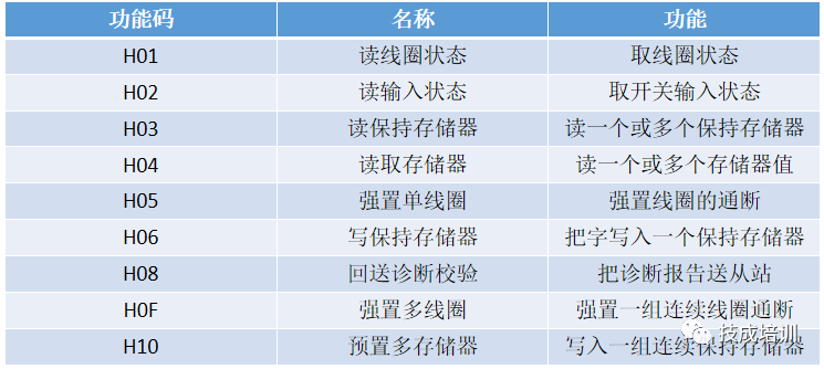
03Common Modbus Function Codes and Functions
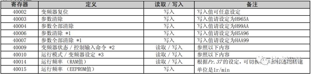
04Mitsubishi Inverter Communication Addresses (More can be found in Mitsubishi E700 Application P220)
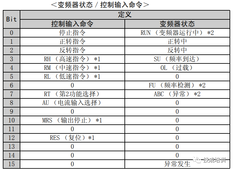
05Instruction Interpretation
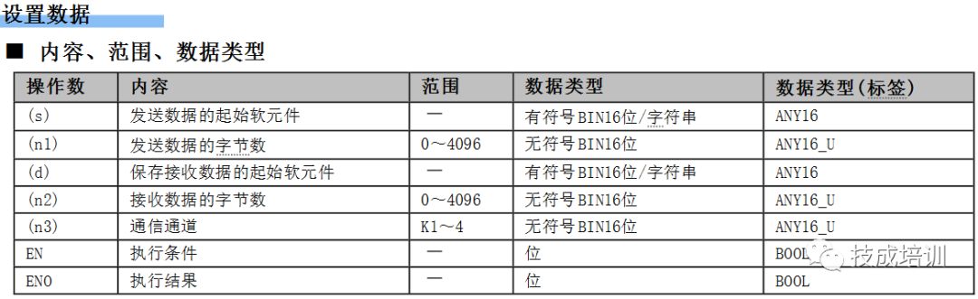
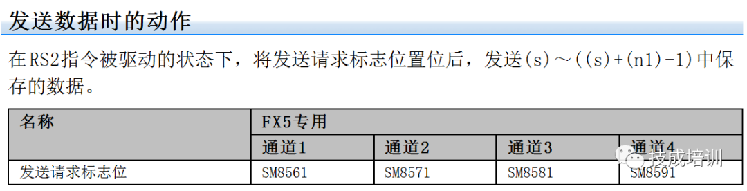
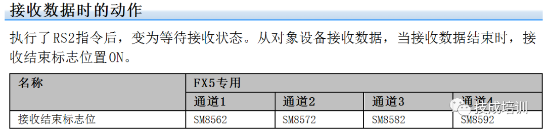
(1) Serial Data Transmission RS2 Instruction Description (Note: When using the instruction, high and low bytes must be reversed)
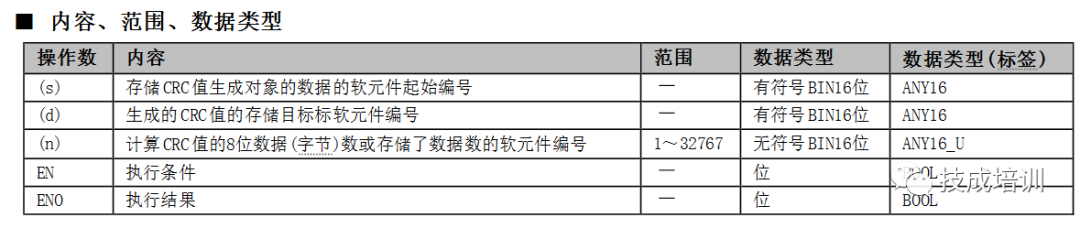
(2) CRC Instruction

3. Implementation of the Task
This case will explain three aspects: hardware wiring, inverter parameter settings, and PLC software program design.
01Hardware Wiring Diagram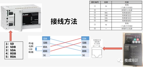
Figure 3-1 Wiring Diagram of FX5U and Mitsubishi Inverter
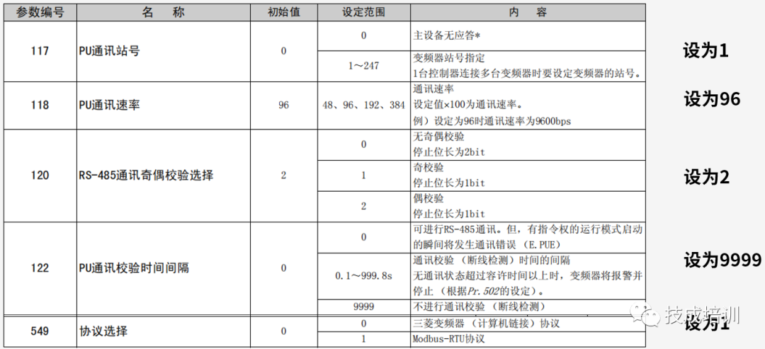
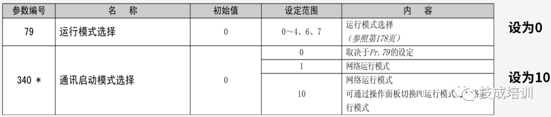
02Inverter Parameter Settings
Before setting parameters, set the inverter parameters to ALLC and set the parameters to 1 to clear all parameters.
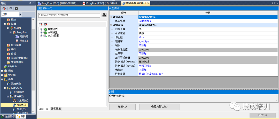
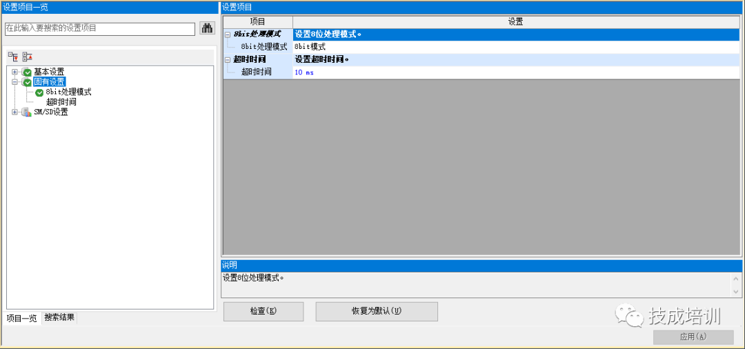
03PLC Software Program Design
Download Source Code for This Article
Scan the QR code below to get the source code for this article!

Source: Technical Training Network Original, Author: Lin Ruihua; Unauthorized reproduction is prohibited, violators will be prosecuted!
HISTORY/Previous Recommendations
3 Essential Tools for Electricians, Easily Accessible via WeChat!
Five Major Electrical Drawing Software (CAD, Eplan, CADe_simu…), Which One Do You Choose?
Latest Electrical CAD Drawing Software, with Detailed Installation Tutorial!
Latest Electrical Drawing Software EPLAN, with Detailed Installation Tutorial!
Common Issues for Beginners Using S7-200 SMART Programming Software (Includes Download Links)
Comprehensive Electrical Calculation EXCEL Sheets, Automatically Generated! No Need to Ask for Electrical Calculations!
Basic Skills in PLC Programming: Ladder Diagrams and Control Circuits (Includes 1164 Practical Cases of Mitsubishi PLC)
Still Can’t Understand Electrical Diagrams? Basic Electrical Diagram Reading Skills and Simulation Software Available for Quick Hands-On Learning!
12 Free Electrical Video Courses, 10GB Software/Ebook Resources, and 30 Days of Free Live Electrical Courses Offered!
Don’t forget to like + view! 
 Click “Read the Original Text” to Learn PLC/Electrician Courses for Free.