There are three control methods for servo motors: pulse, analog, and communication. How should we choose the control method for servo motors in different application scenarios?
1. Pulse Control Method for Servo Motors
In some small standalone devices, using pulse control to achieve motor positioning is the most common application method. This control method is simple and easy to understand.
The basic control idea is: the total number of pulses determines the motor displacement, and the pulse frequency determines the motor speed. When using pulses to control the servo motor, the servo motor manual usually contains a table like the following:
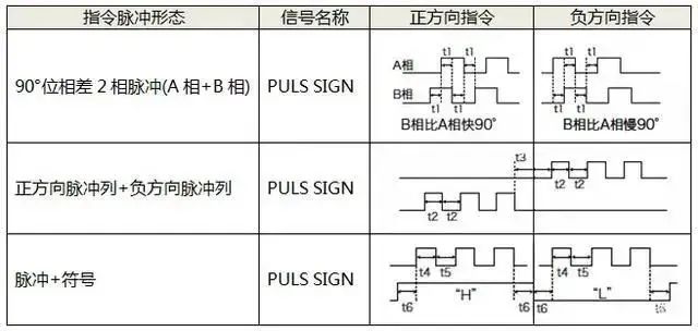
Although all are pulse controls, the implementation methods are different:
First, the driver receives two channels (A and B) of high-speed pulses. The phase difference between the two pulse channels determines the rotation direction of the motor. As shown in the figure, if B is 90 degrees ahead of A, it is a forward rotation; if B is 90 degrees behind A, it is a reverse rotation.
During operation, the two-phase pulses are alternating, so we also call this control method differential control. The differential characteristic indicates that this control method has higher anti-interference capability, making it preferable in applications with strong interference. However, this method requires two high-speed pulse ports for one motor shaft, which is not suitable in situations where high-speed pulse ports are limited.
Second, the driver still receives two channels of high-speed pulses, but only one pulse is active at a time. When one pulse is in the output state, the other must be in an inactive state. When using this control method, it is essential to ensure that only one pulse is output at the same time. One pulse output runs in the positive direction, while the other runs in the negative direction. Similar to the previous case, this method also requires two high-speed pulse ports for one motor shaft.
Third, only one pulse signal needs to be given to the driver, and the motor’s forward and reverse operation is determined by one direction IO signal. This control method is simpler, and it occupies the least resources of high-speed pulse ports. In general small systems, this method can be preferred.
2. Analog Control Method for Servo Motors
In applications where servo motors are required to achieve speed control, we can use analog signals to control the motor’s speed, where the value of the analog signal determines the running speed of the motor.
There are two ways to use analog signals: current or voltage.
Voltage method: It only requires adding a certain voltage to the control signal terminal. In some scenarios, even using a potentiometer can achieve control, which is very simple. However, using voltage as a control signal can be easily interfered with in complex environments, leading to unstable control.
Current method: It requires a corresponding current output module, but the current signal has strong anti-interference capability and can be used in complex scenarios.
3. Communication Control Method for Servo Motors
Common communication methods for controlling servo motors include CAN, EtherCAT, Modbus, and Profibus. Using communication methods to control motors is currently the preferred control method for some complex and large system applications. In this method, the size of the system and the number of motor shafts are easy to tailor, without complicated control wiring. The constructed system has high flexibility.
4. Expansion Section
1. Torque Control for Servo MotorsThe torque control method sets the output torque of the motor shaft to the outside through external analog input or direct address assignment. For example, if 10V corresponds to 5Nm, when the external analog value is set to 5V, the motor shaft outputs 2.5Nm. If the motor shaft’s load is less than 2.5Nm, the motor is in an acceleration state; when the external load equals 2.5Nm, the motor is in a constant speed or stop state; when the external load exceeds 2.5Nm, the motor is in a deceleration or reverse acceleration state. The set torque can be changed instantly by modifying the analog value or through communication to change the corresponding address value.This is mainly applied in winding and unwinding devices that have strict requirements on material stress, such as winding devices or fiber optic drawing equipment, where the torque setting must change according to the variation in the winding radius to ensure that the material’s stress does not change with the winding radius.2. Position Control for Servo MotorsPosition control mode generally determines the rotation speed through the frequency of externally input pulses and determines the rotation angle through the number of pulses. Some servos can also directly assign values to speed and displacement through communication. Since the position mode can strictly control both speed and position, it is generally used in positioning devices, CNC machine tools, printing machinery, etc.3. Speed Mode for Servo MotorsRotation speed can be controlled through analog signals or pulse frequency input. In the case of an upper-level control device with external PID control, the speed mode can also perform positioning, but the motor’s position signal or direct load’s position signal must be fed back to the upper-level machine for computation. The position mode also supports direct load external loop detection position signals. In this case, the encoder at the motor shaft end only detects the motor speed, while the position signal is provided by the direct final load detection device, which has the advantage of reducing errors in the intermediate transmission process and increasing the overall system’s positioning accuracy.4. Discussing the Three LoopsServo systems generally have three-loop control, known as three loops, which are three closed-loop feedback PID adjustment systems.The innermost PID loop is the current loop, which operates entirely within the servo driver. It detects the output current of each phase to the motor through Hall devices and feeds back to the current setting for PID adjustment, thus achieving the output current as close as possible to the set current. The current loop controls the motor’s torque, so the driver’s computation is minimal in torque mode, and the dynamic response is the fastest.The second loop is the speed loop, which uses the signal from the motor encoder for feedback PID adjustment. The PID output of this loop directly corresponds to the current loop’s setting. Therefore, when controlling the speed loop, it contains both the speed and current loops. In other words, any mode must use the current loop; the current loop is fundamental to control. While controlling speed and position, the system is also controlling current (torque) to achieve corresponding control of speed and position.The third loop is the position loop, which is the outermost loop. It can be constructed between the driver and motor encoder or between the external controller and motor encoder or final load, depending on the actual situation. Since the output of the position control loop is the setting of the speed loop, when the system operates in position control mode, all three loops are computed, resulting in the largest computational load and the slowest dynamic response speed.
☞ Source: Jun Tuo Robotics
☞ Advertising Cooperation: Sun Ha 13811718902
Statement: If there are copyright issues with the videos, images, or text used in this article, please inform us immediately. We will confirm the copyright based on the proof materials you provide and pay fees according to national standards or delete the content immediately!
Statement: If there are copyright issues with the videos, images, or text used in this article, please inform us immediately. We will confirm the copyright based on the proof materials you provide and pay fees according to national standards or delete the content immediately!