For every beginner in microcontrollers, the first program is almost always to light up an LED, which is as classic as the “hello world” in software engineering. It’s simple but filled with many memories. I still remember the experience of learning about microcontrollers. Back then, a classic 8051 microcontroller like the AT89C52 cost about 8 dollars, and I had to buy resistors and capacitors myself (the school didn’t have a development lab at that time). Sometimes, I had to spend 4 yuan on bus fare to go to the electronics market just to buy a few resistors and LEDs, buying them one by one: 10 cents for 2 resistors and 10 cents for 1 LED of type M5. Then I joyfully soldered and connected everything, only to end up burning some components… Looking back, it’s quite emotional!
Back to the point, I believe there are several reasons why lighting up an LED is the first program in microcontroller learning:
1. Learn to use Keil software to create a microcontroller project, set up program files, configure the software, and compile programs.
2. Learn to analyze circuits and validate them.
3. Learn to use Proteus to draw circuit schematics and debug simulations.
4. Understand the basic process of a small experiment.
Considering the above points, doing this experiment seriously is very necessary to enhance learning interest.
What is an LED?
LED stands for Light Emitting Diode. It emits visible light, and the commonly used types emit red, yellow, and green light. In products, red is often used to indicate system errors, green is used to indicate normal operation, and yellow is used for warnings. Depending on application needs, LEDs come in various forms, as shown in the figure.
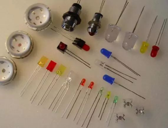
The image shows square, round, and surface-mounted LEDs in different colors. Generally, the color of the emitted light matches the color of the LED casing. When using them, several points must be noted:
1. Pin identification: This example uses a 2-pin LED; the longer pin is the positive electrode, and the shorter pin is the negative electrode.
2. Operating voltage: Typically 1.2~2.2V
3. Operating current: 2mA~20mA
How to light it up?
Once you know the basic parameters of the LED, you can design the circuit according to your needs. Oh! What is a circuit?
A circuit refers to a loop composed of a power supply, wires, electrical appliances, and switches (something like that).
Therefore, the circuit to light up the LED must include the defined components:
1. Power supply: This example uses a 5V DC power supply.
2. Wires: In this example, we use Proteus for simulation, and the connections serve as wires.
3. Electrical appliance: The LED, of course, requires a resistor as well.
4. Switch: In the simulation, “Run” acts as the switch.
Alright, let’s witness the growth of the LED:
1. Calculation: Referring to the LED parameters, this example uses a large round red LED of type M3 for demonstration. Its working current can be set to 3mA, which is bright enough; the brightness of the LED is related to the current. The working voltage is set at 2V (based on measured data). So, how do we meet this condition? The power supply is 5V, while the LED only needs 2V, leaving us with 3V. What to do? This is where the resistor comes in; it is a device that can “consume voltage”. The remaining 3V will be applied across it. Thus, it is clear that Vled = 2V, Vr = 3V, I = 3mA. The resistor and LED should be connected in series, no need to explain. However, we still need one more parameter—the resistance value. At this point, Ohm’s Law comes into play: R = U / I = 3V / 3mA = 1K.
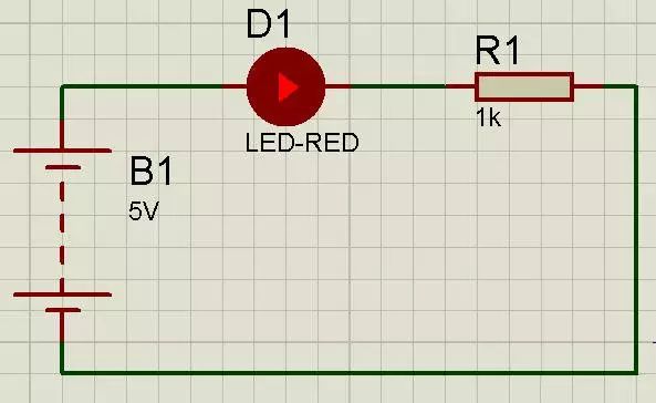
2. Draw the simulation circuit diagram: I won’t go into the process; just look at the image.
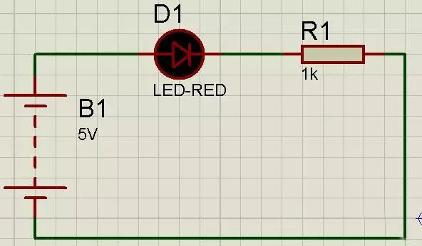
After running the simulation.
Add an ammeter and voltmeter to measure the data and see if there are any deviations from the calculations.
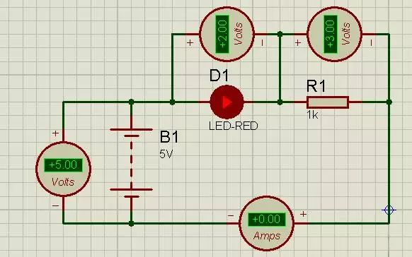
OK, correct.
How does the microcontroller control the LED?
In the above image, we directly apply voltage to the LED to light it up. This control method relies on controlling the switch’s on/off state, just like the lights in a household. The emergence of microcontrollers has opened the intelligent era of electronic devices. In another way, we use the microcontroller to control the LED’s on/off state, and the microcontroller executes programs to output the desired results, truly realizing human thoughts.
The microcontroller is a digital circuit, with output/input only distinguishing between high level 1 and low level 0. Typically, a voltage range of 0~0.4V is defined as low level, while greater than 2V is defined as high level. The figure shows the circuit diagram of the microcontroller controlling the LED.
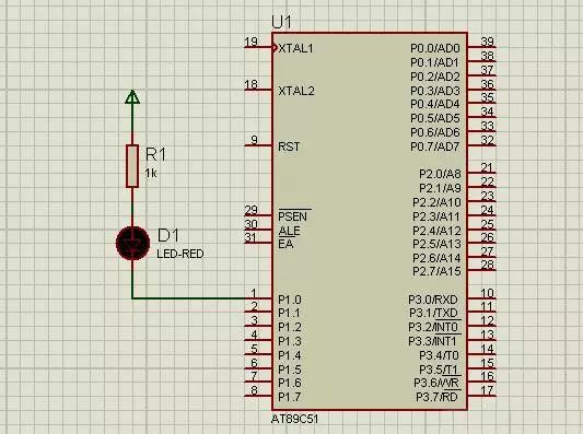
PS: Since this is a simulation, I’ve taken a shortcut and omitted the clock circuit, power circuit, and reset circuit from the diagram.
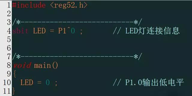
Connect the negative electrode of the LED to the microcontroller’s P1.0 pin, and the positive electrode through the resistor R1 to +5V. The principle is the same; when the microcontroller outputs a low level 0, a potential difference is created across the LED and resistor, equivalent to the “5V power supply” in the above diagram, thus meeting the LED’s parameters and lighting it up. When the microcontroller’s P1.0 pin outputs a high level, the potential difference is approximately 0, which does not meet the requirements for the LED to light up, causing the LED to turn off. To achieve this effect, we must program the microcontroller with our “idea”; this is where the program comes into play.
Program writing: Create a new C language program project in Keil. The code is as follows:
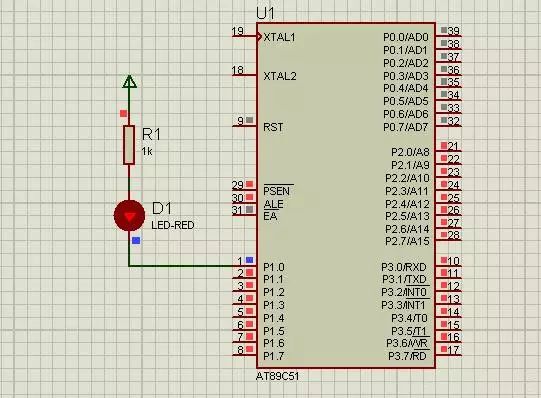
Run the simulation, and you can see the LED lighting up. I won’t elaborate on the specific steps; there are plenty of resources online.
But is this good? Well, by this point, the process has basically been completed. However, this program isn’t very meaningful. When we need to light up multiple LEDs, we would need to define each LED like this: sbit LED1 = …; sbit LED2 = …; then assign values. You might say, “It’s simple, just assign values to the ports, like P1 = 0x6D, and that’s it.” But what if these LEDs are not all on the same port? Then we still have to define and assign values one by one. Is this good? Maybe not. The following program example encapsulates the logic of lighting an LED into a function, which only implements the logic function of lighting the LED. When using it, you can set the function parameters according to the hardware connections, hoping to spark some ideas.

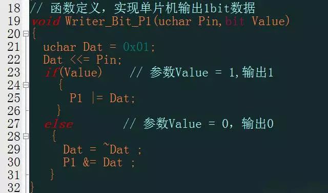
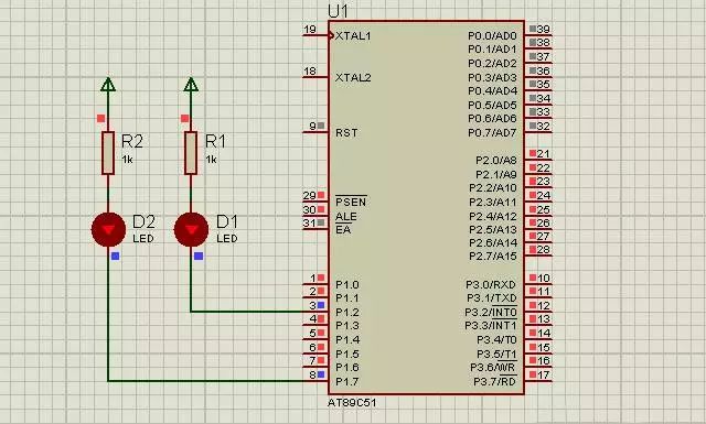
The result of running is that P1^2 and P1^7 output low level, lighting up the LED.