Modbus RTU Communication
Overview of Modbus RTU Communication
In modern highly integrated industries, communication between PLCs is often used. Common communication protocols include Modbus, Profibus DP, Profinet, CANOPEN, etc. Today, we will explain how to perform Modbus RTU communication between two PLCs using Siemens TIA Portal.
Before establishing communication, we must meet the following software and hardware requirements:
-
1. A computer with TIA V16 Portal software;
-
2. Two Siemens series PLCs, must be compatible with TIA Portal V16;
-
3. A DP9 pin male connector (for 1200), a DP15 pin male connector (for 1500), and a two-core shielded cable (specification 0.5 square);
-
4. The communication module model specifications for today’s experiment are as follows:
CM1241RS422/485 Order Number: 6ES7 241-1CH320XB0;
CMPtP RS422/485HF Order Number: 6ES7 541-1AB00-0AB0;
The images below show the communication modules and DP connectors needed today;
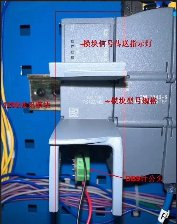
1200 side communication module
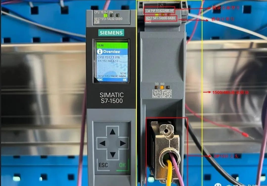
1500 side communication module
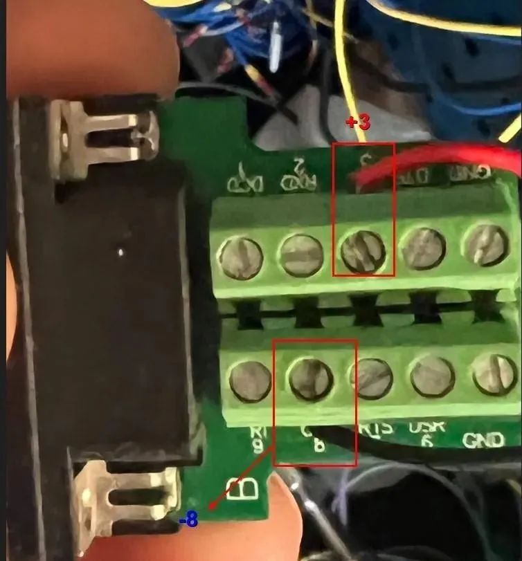
DP9 pin male connector for 1200
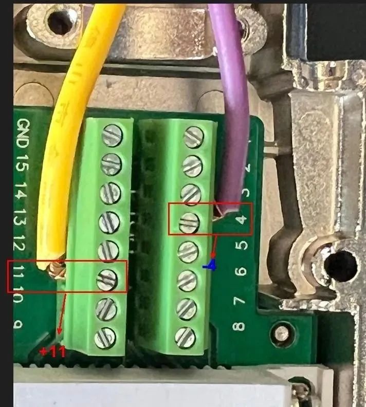
DB15 pin male connector for 1500
Modbus wiring for 1200 and 1500:
1200 PLC side 1500 PLC side
3+ 11+
8- 4-
Configuration master station (1200 side):
1.) Create a project and add the CPU and RS485 module as shown in the figure below:
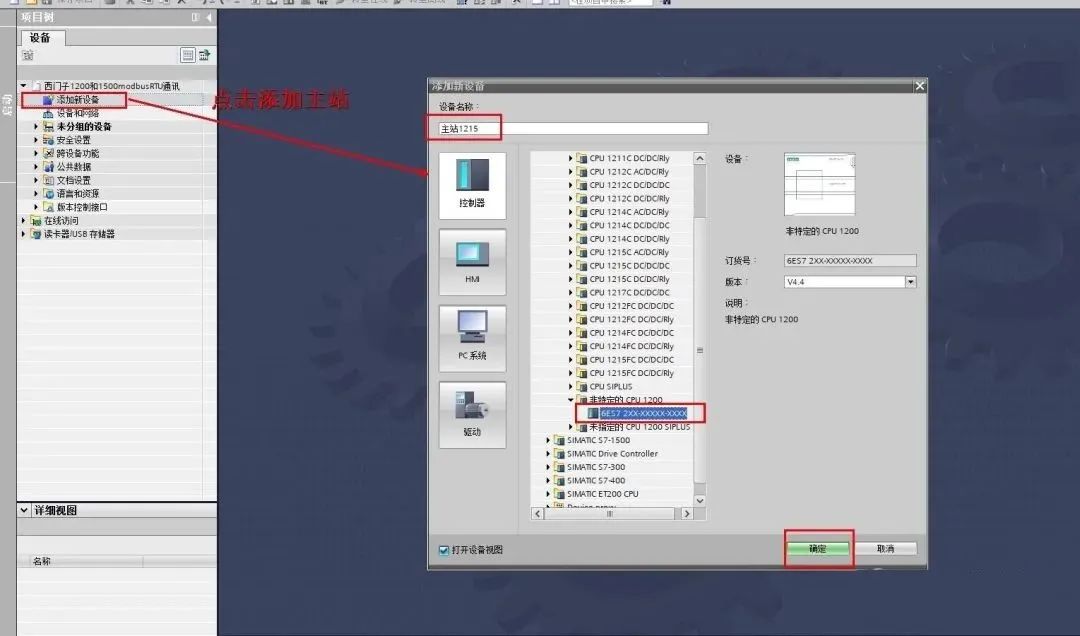
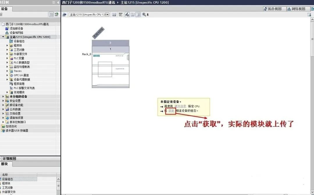
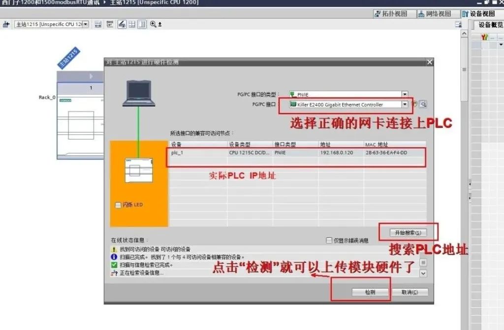
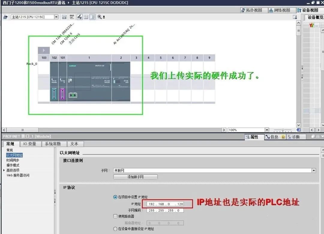
2.) Hardware setup is complete; we will set the parameters for the CM1241-R485 module:
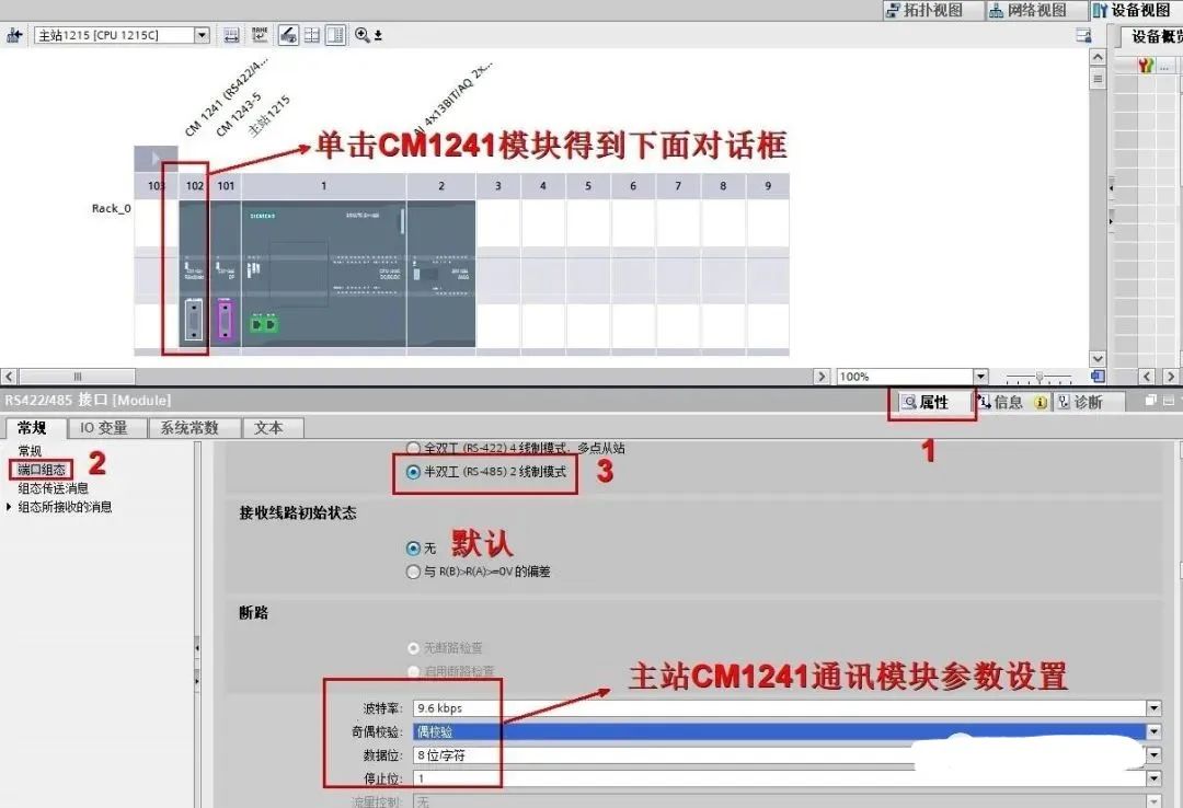
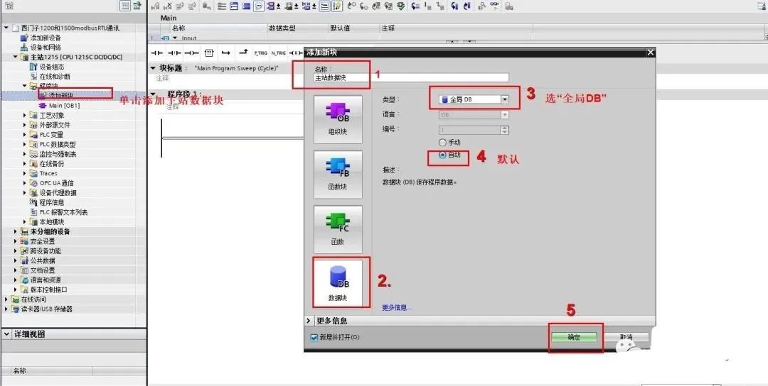
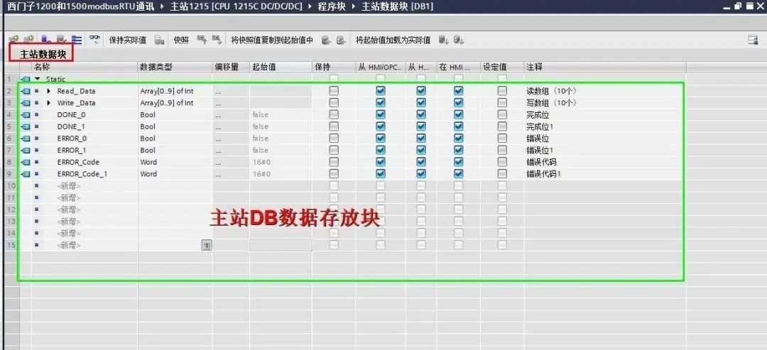
3.) Create a DB block for storing data for the 1200 PLC (master station):
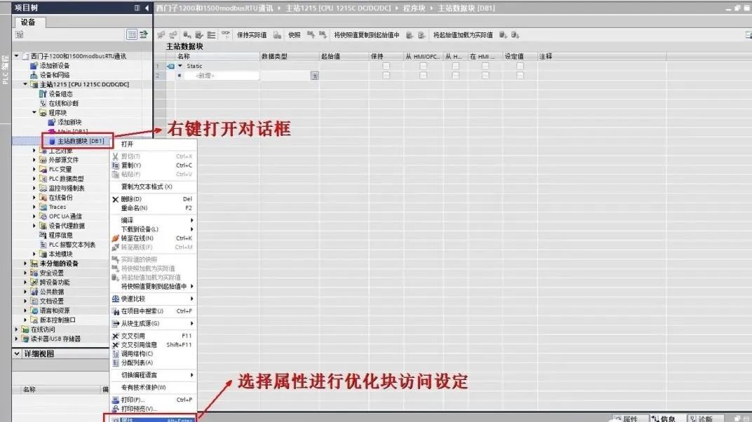
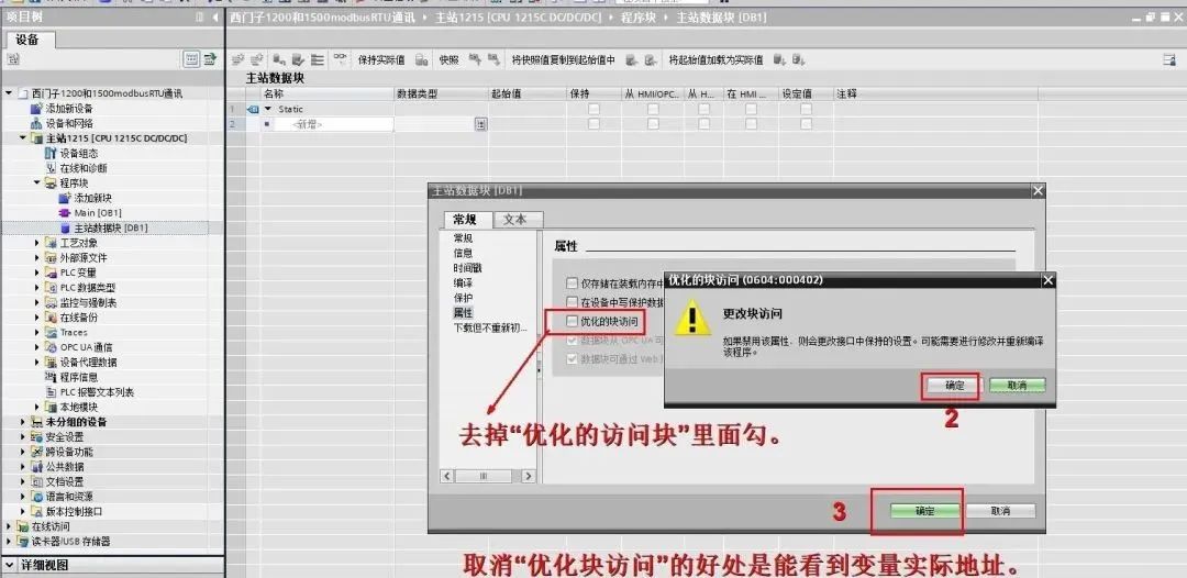
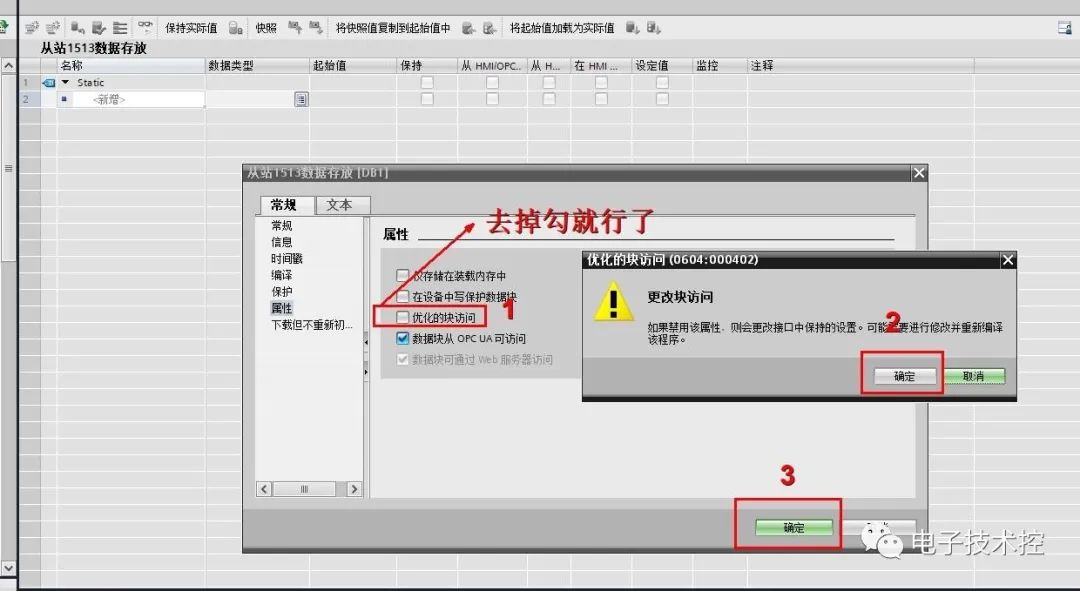
Modify the DB block for “optimized access”.
4.) Create the required data:
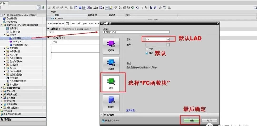
5.) Add an FC function block:
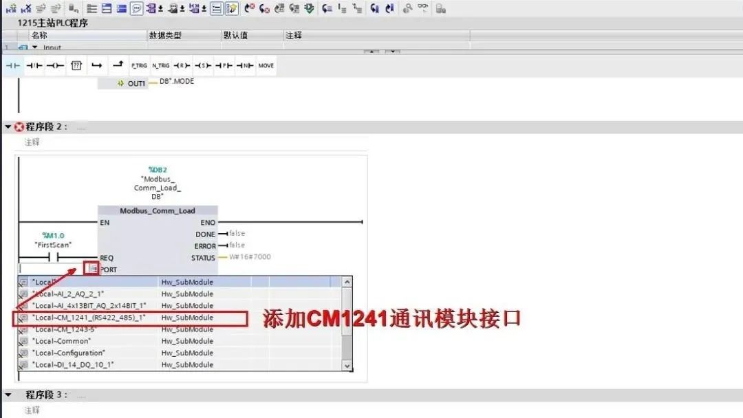
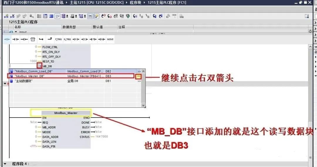
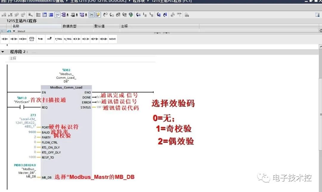
6.) We will write the program into the FB program segment and set the Modbus_Comm_Load pin parameters:
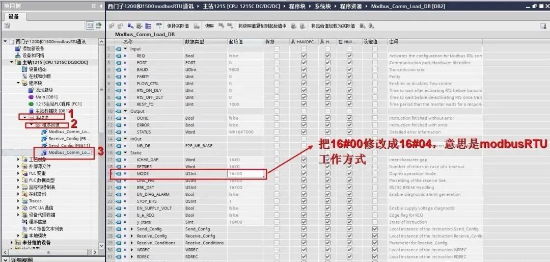
7.) Since the Modbus_Comm_Load block defaults to RS232 mode, we need to change it to RS485 mode. There are two ways to modify it: the first is to change the “MODE” parameter in the Modbus_Comm_Load background DB block from 16#00 to 16#04 as shown below:
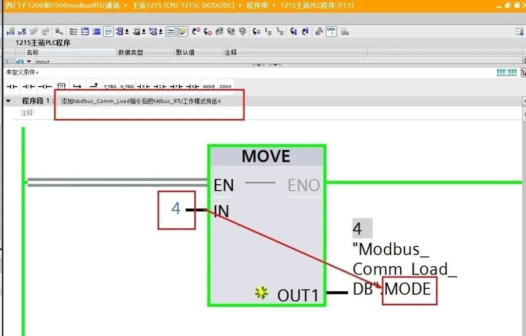
The second method is to use the “move” instruction to pass a 4 to Modbus_Comm_Load_MODE as shown below:
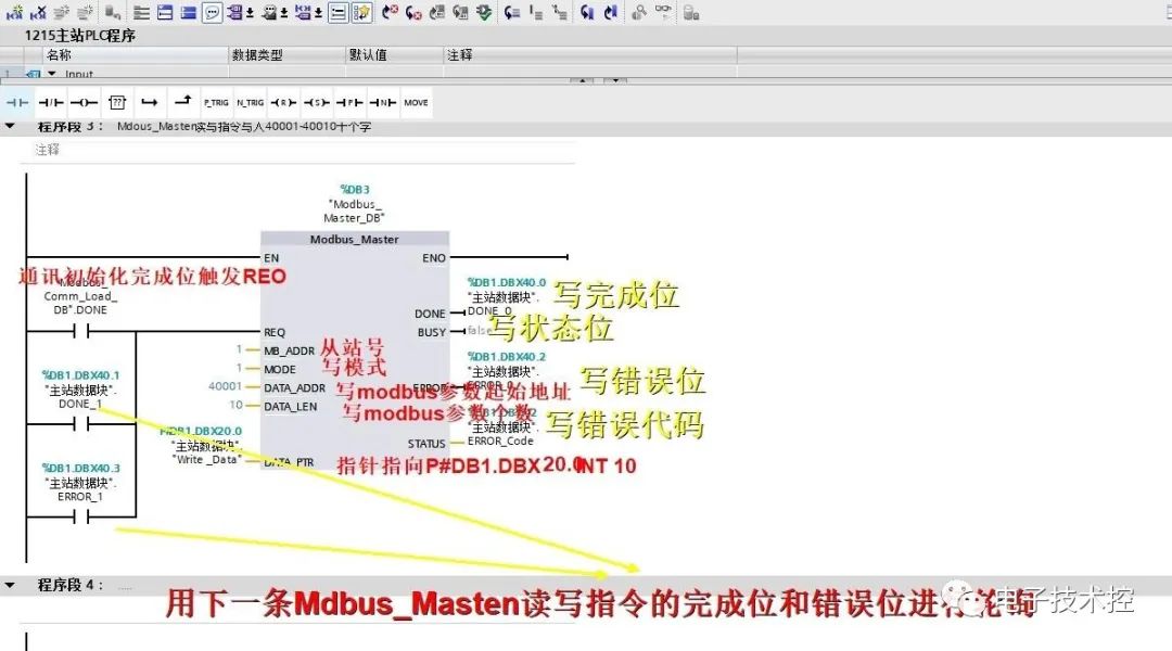
Set the pin parameters for the Modbus_Master function block:
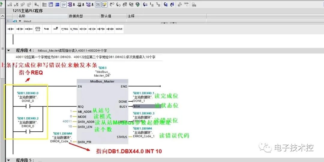
8.) Test the program:
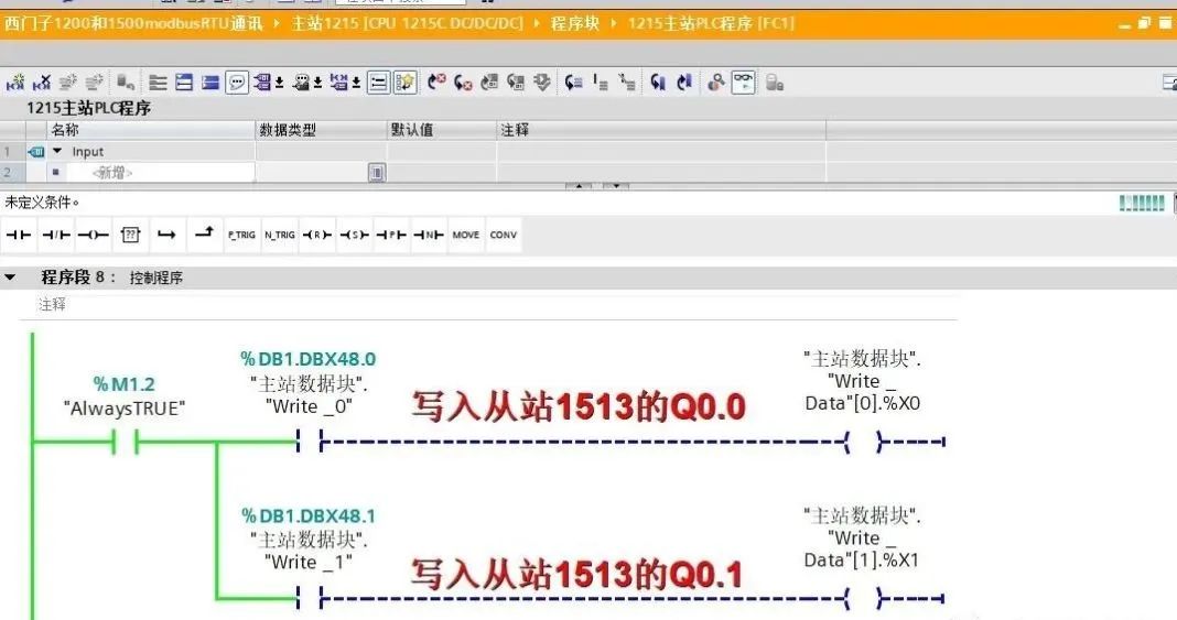
Write to the slave 1500 Q area:
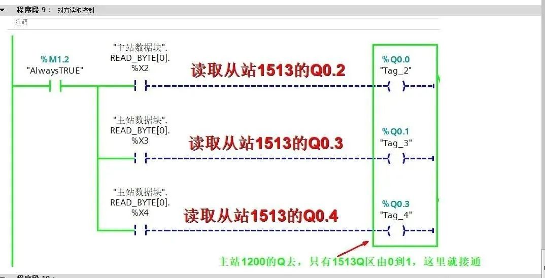
Read from the slave 1500 Q area:
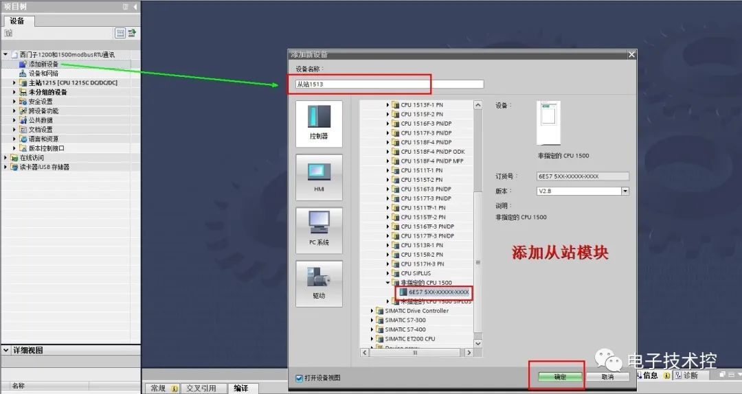
Complete the master station program, then configure the slave PLC:
10.) Create a project and add the CPU and communication modules as shown in the figure below:
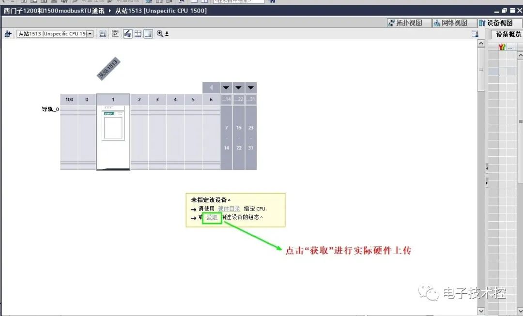
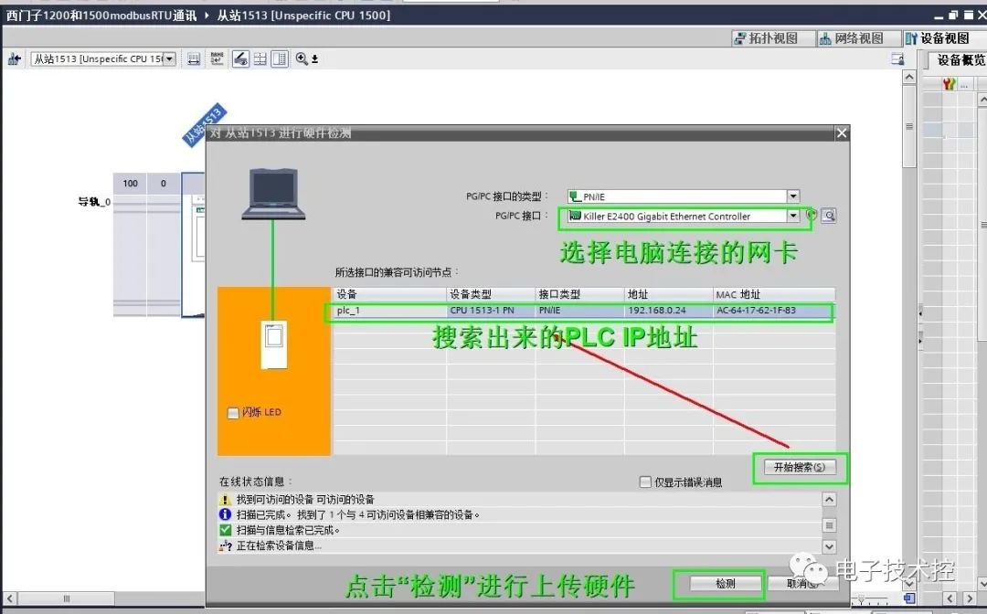
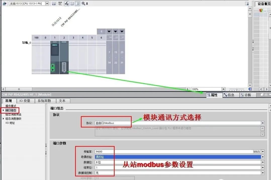
11.) Set the PtP-RS422/485 communication module parameters as shown below:
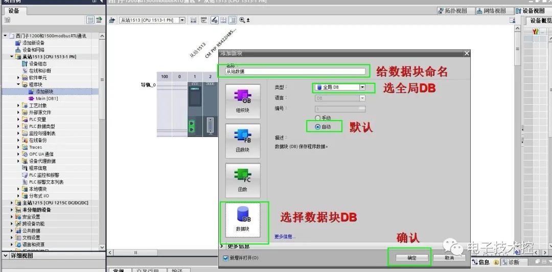
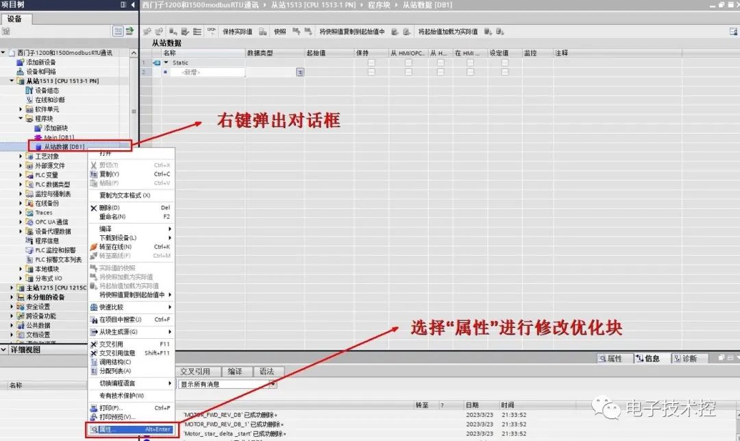
12.) Add a global data background DB block:
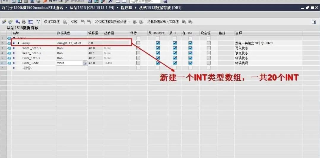
13.) Create storage data:
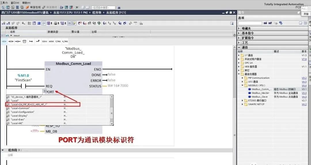
14.) We start writing the program, adding a “Modbus_comm_Load” communication initialization instruction block to the FB program segment and setting the corresponding pin parameters:
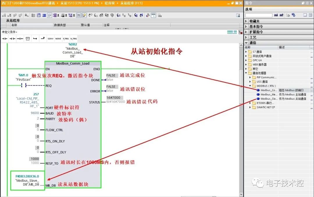
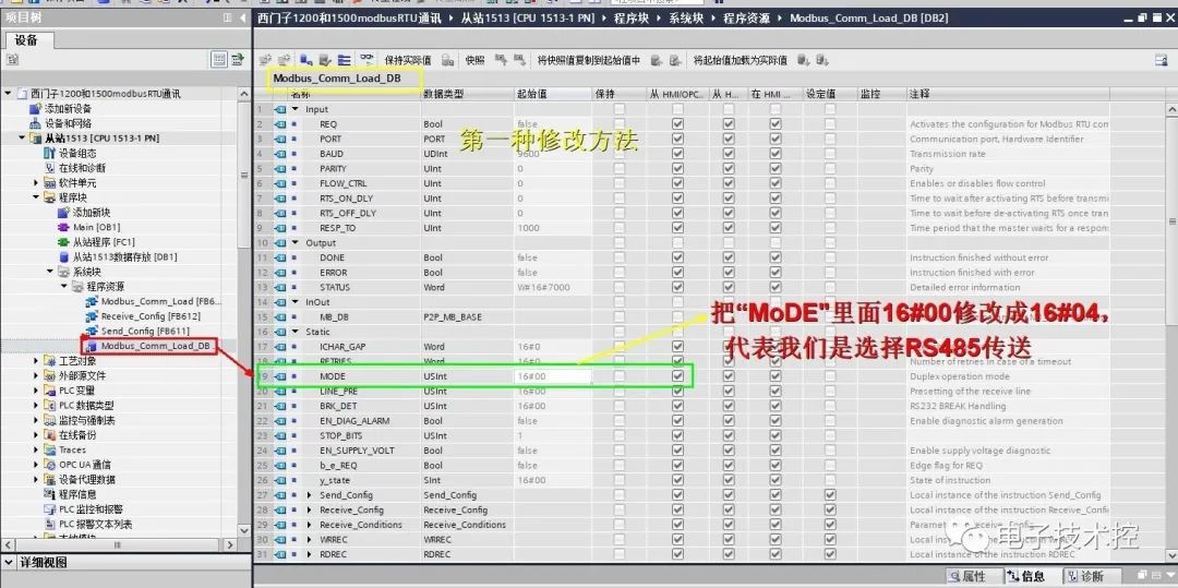
Since the “Modbus_comm_Load” function block defaults to RS232, and we enable RS485, modifications are necessary. The first method is to directly modify Modbus_comm_Load as shown below:
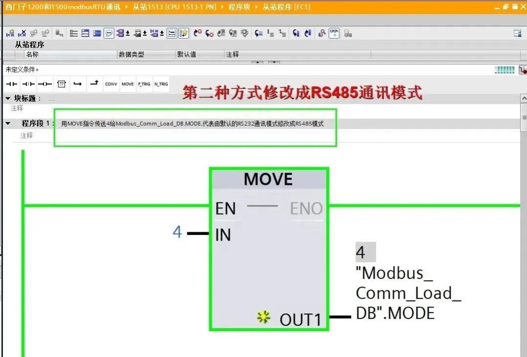
The second method is consistent with the previous modification of the 1200 communication data block as shown below:
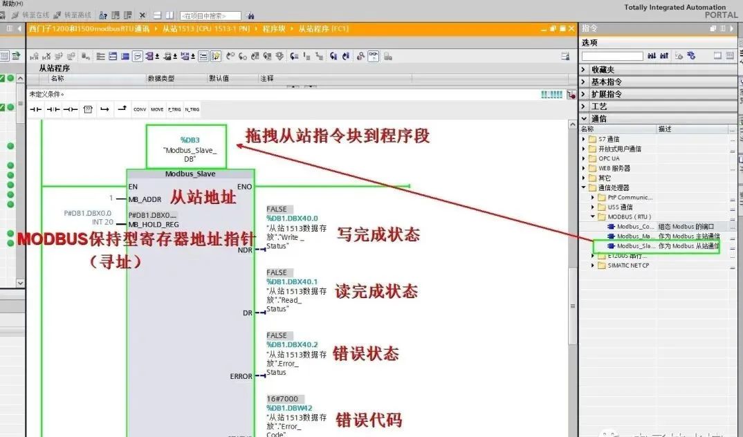
15. Add the slave instruction block:
16. Test the program:
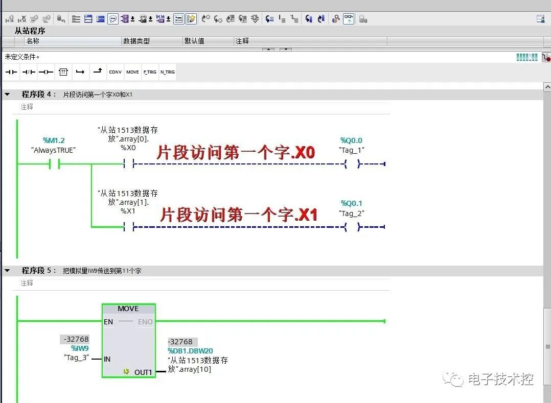
The master station 1200 writes to the slave 1500’s Q0.0, Q0.1;
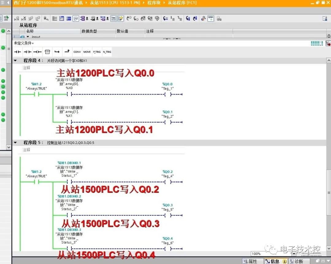
The slave 1500 writes to the master station 1200’s Q0.2, Q0.3, Q0.4;
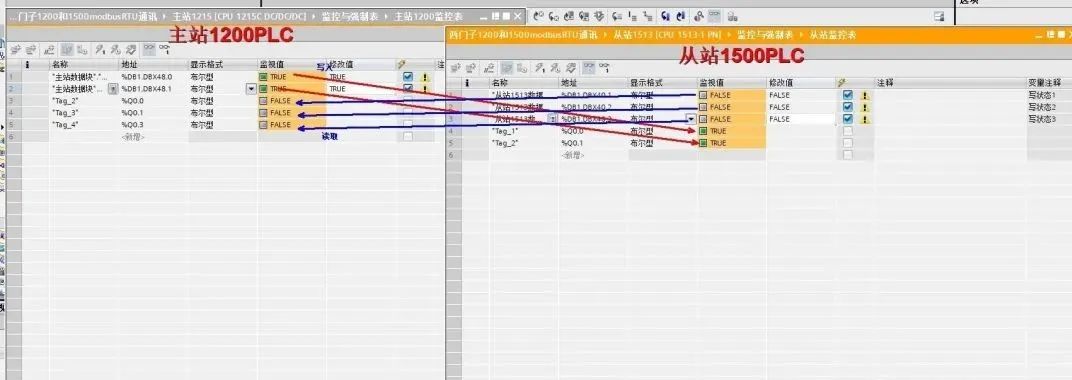
Monitor the program:
The above article briefly introduces the Modbus RTU communication between Siemens 1200 PLC and Siemens 1500 PLC. After real machine testing, the read and write operations are correct. Due to time constraints and limited expertise, there may be unclear or incorrect information in the article. Please feel free to leave comments for discussion!
Disclaimer: This article is reproduced from the internet, and the copyright belongs to the original author. If there are any copyright issues, please contact us for deletion. Thank you!

[Siemens Example Program]