 Don’t be afraid of complex PID tuning and mismatched program logic in industrial temperature control debugging! Follow the actual program points step by step, and control will be easy to implement. Completely align with your program data blocks and logic, and achieve the entire process from signal conversion to PID adjustment and pump-valve coordination in 4 steps, with practical implementation in one go!
1. Core Requirements for Temperature Control and Pump-Valve Coordination
1. Temperature Acquisition: The PLC collects sensor signals through the analog module, converting them to an actual water temperature of 0-50℃;
2. PID Closed-Loop Temperature Control: Call the PID function block to switch between automatic/manual modes to adjust the valve opening;3. Pump-Valve Coordination: Control the start/stop of the cooling pump based on the valve opening, with a delay loop to prevent frequent switching;4. Mode Switching: Support seamless switching between manual/automatic modes, with automatic switching to manual in case of PID failure;5. Fault Alarm: Water shortage faults trigger alarms and self-locking, with a reset button to clear the alarm.
2. Core Data Block Definitions
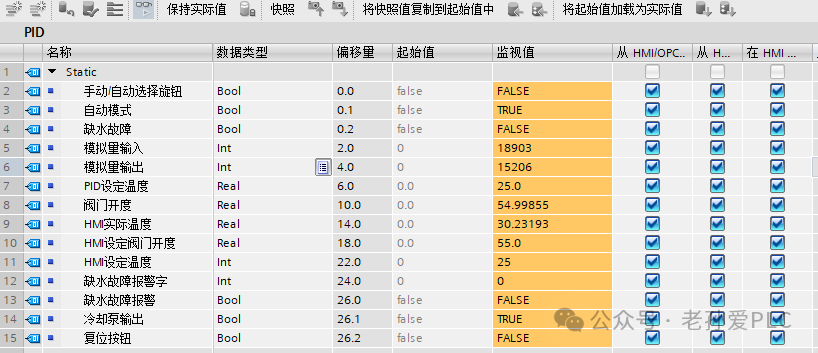
3. Programming PID Temperature Control and Pump-Valve Coordination in 4 Steps
Step 1: Analog Signal Conversion (Temperature Acquisition)
Core Logic: Convert the raw analog signal from the sensor to the actual temperature, and convert the HMI set temperature to a real number format supported by PID.
Operation Steps:
1. Call the NORM_X instruction, set the enable bit (EN) to 1, parameter settings: MN=5529, MAX=27648, VALUE=DBW2 (analog input), OUT=DBD14 (temporary value);
2. Call the MUL_R instruction, set the enable bit (EN) to 1, parameter settings: IN1=DBD14 (temporary value), IN2=50.0, OUT=DBD14 (final actual temperature of 0-50℃);
3. Call the CONV instruction, set the enable bit (EN) to 1, parameter settings: IN=DBW22 (HMI set temperature), OUT=DB47.DBD6 (PID set temperature, real number format).
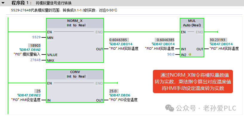
Step 2: Calling and Adjusting the PID Function Block
Core Logic: In automatic mode, the PID calculates the valve output based on the deviation between the actual temperature and the target temperature; in manual mode, switch to the HMI set opening.
Operation Steps:
1. Call the PID_Compact function block, set the enable bit (EN) to 1, conditions: DBX0.1 (automatic mode) = DBX0.0 (knob switch not manual) and (no PID fault);
2. Function block parameter configuration: PV=DBD14 (actual temperature), SP=DBD6 (PID set temperature), OUT=DBW4 (analog output), MAN=DBX0.0 (automatic enable), MAN_VALUE=DBD18 (manual opening);
3. Call the NORM_X instruction, parameter settings: MN=0, MAX=27648, VALUE=DBW4, OUT=DBD10 (temporary value), then call the MUL_R instruction to multiply by 100.0 to get the 0-100% valve opening (DBD10).
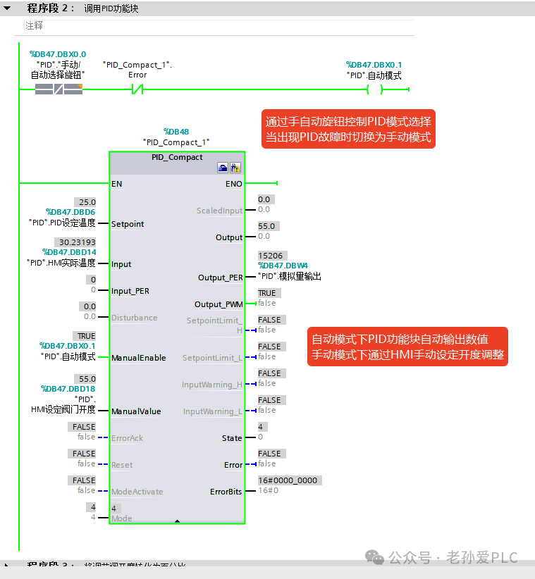
Step 3: Valve and Cooling Pump Coordination Control
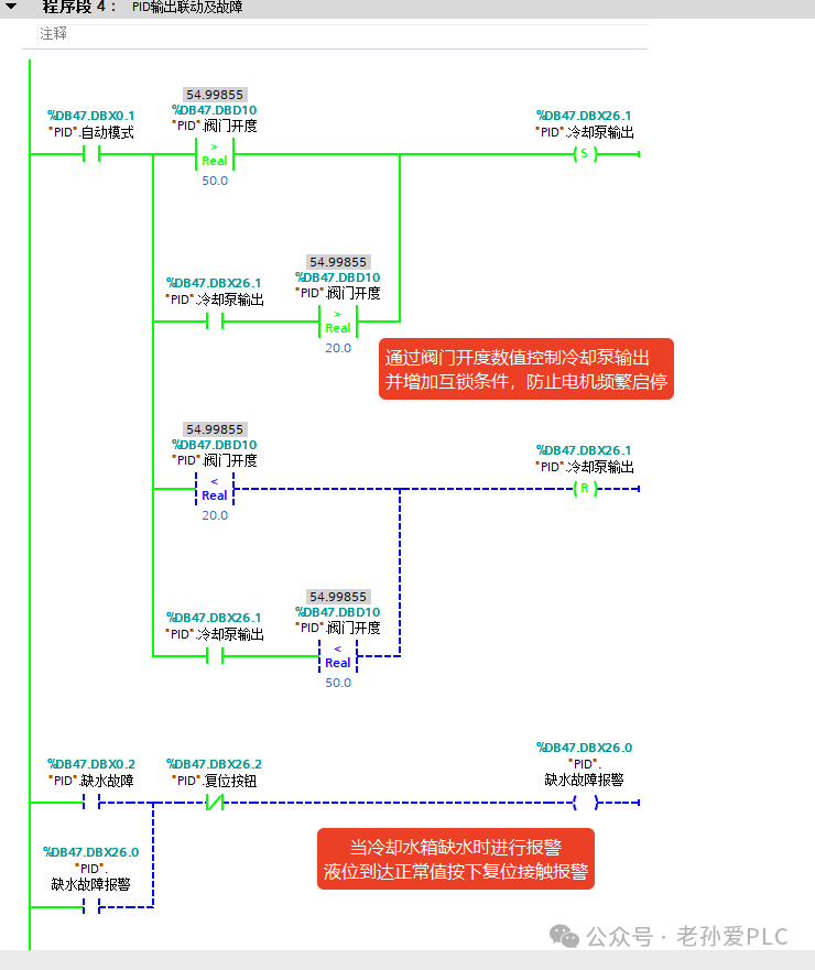
Core Logic: Control the start/stop of the cooling pump based on the valve opening output from PID, with a delay loop to prevent frequent switching.
Operation Steps:
1. Pump Start Condition: DBX0.1 (automatic mode) = 1 + DBD10 (valve opening) > 50.0, set DBX26.1 (cooling pump output) using the S instruction;
2. Pump Hold Condition: DBX26.1 (pump running) = 1 + DBD10 > 20.0, keep the pump running;
3. Pump Stop Condition: DBD10 (valve opening) < 20.0, reset DBX26.1 using the R instruction;
4. Emergency Stop: When DB47.DBX0.2 (water shortage fault) = 1, directly reset DBX26.1 (stop pump) to prioritize safety.
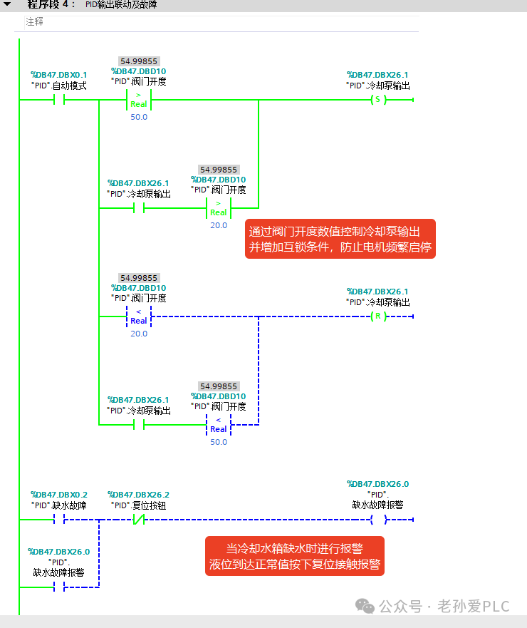
Step 4: Manual and Automatic Mode Switching and Fault Alarm
Core Logic: In automatic mode, PID closed-loop control; in manual mode, directly control the device, with fault alarms self-locking to prevent false alarms.
Operation Steps:
1. Automatic Mode (DBX0.0=0): Set DBX0.1 to 1, the PID function block automatically adjusts the valve opening, and the pump coordinates based on the opening;
2. Manual Mode (DBX0.0=1): Reset DBX0.1, set the MAN end of the PID function block to 1, directly control DBW4 (analog output) and DBX26.1 (pump start/stop) through HMI setting DBD18 (valve opening);
3. Fault Alarm: When DBX0.2 (water shortage fault) = 1, self-lock DBX26.0 (water shortage fault alarm);
4. Alarm Reset: Press DBX26.2 (reset button) to reset DBX26.0 (water shortage fault alarm).
4. Key Reminders for On-Site Debugging (Guide to Avoiding Detours)
1. Parameter Matching: The thresholds for opening the pump at 50% and stopping at 20% must align with the PID response speed; otherwise, slight adjustments in PID may cause the pump to start and stop frequently;
3. Switching Techniques: The initial valve opening in manual mode should be similar to the PID automatic output value; avoid sudden changes in opening to prevent rapid temperature fluctuations that the equipment cannot withstand.
Learn technology solidly, and improve a little every day! Do your best to help more people!