In the field of industrial automation, PLCs (Programmable Logic Controllers) serve as core control devices, and their programming capabilities directly determine the stability and efficiency of automation systems. This article presents a classic case of material handling cart control program design, showcasing the programming ideas and practical techniques of the Mitsubishi FX series PLC from task description, basic knowledge to specific implementation. Whether you are a novice engineer or a technician looking to enhance your skills, this case will help you master the core logic of sequential control and ladder diagram programming methods.
Case Task Control Description
The automatic control of the material handling cart is a fundamental scenario in factory material handling systems, with the core being precise position control and action switching achieved through PLC. The specific control requirements are as follows:
-
Initial State: The cart stops at the original position SQ1 and starts running after pressing the start button SB1.
-
First Cycle:
-
The motor rotates forward, and the cart moves to SQ2.
-
After hitting SQ2, the motor reverses, and the cart retreats to SQ1 and stops.
Second Cycle:
-
After stopping for 30 seconds, it moves forward again until it hits SQ3.
-
After triggering SQ3, it reverses and returns to SQ1 to stop.
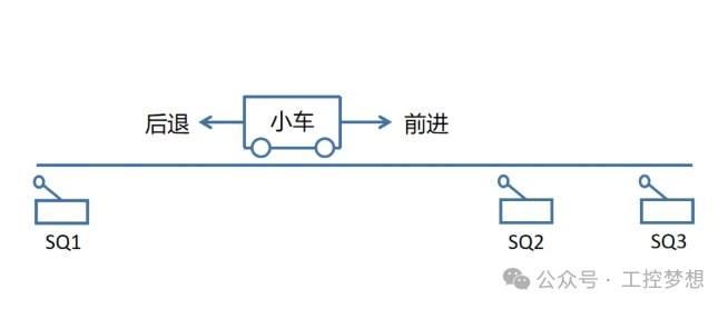
Figure 1-1: Schematic of Material Handling Cart Operation
Related Basic Knowledge
Before programming, ensure that you master the following core knowledge points. Mitsubishi provides supporting basic courses, and it is recommended to study them before practicing the case:
Essential Prerequisite Courses
-
“Mitsubishi Key Difficulties Analysis – Basic Edition”
-
GX Works2 Software Operation: Watch here
-
Application of SFC Programs: Watch here
-
“Mitsubishi PLC Case Analysis – Basic Edition”
-
Motor Automatic Return Case: Watch here
Core Technical Concepts
1. Five Programming Languages of PLC
The International Electrotechnical Commission (IEC) specifies five standard programming languages for PLCs. This case mainly uses Ladder Diagram (LD) and Sequential Function Chart (SFC):
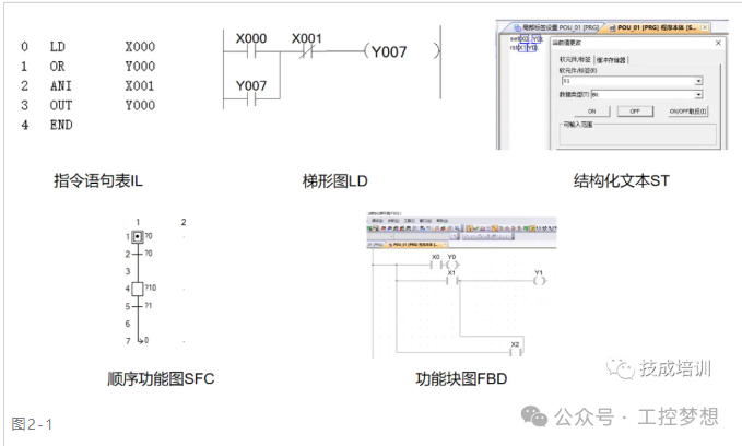
Figure 2-1: Types of Five Programming Languages: Instruction List IL, Ladder Diagram LD, Structured Text ST, Sequential Function Chart SFC, Function Block Diagram FBD
2. Principles of Sequential Control
Sequential control is a control logic executed in a predetermined order, where the next step cannot be entered until the current step is completed. As shown in Figure 2-2, only when Step 1 is completed and conditions are met will Step 2 be triggered, forming a strict execution sequence.
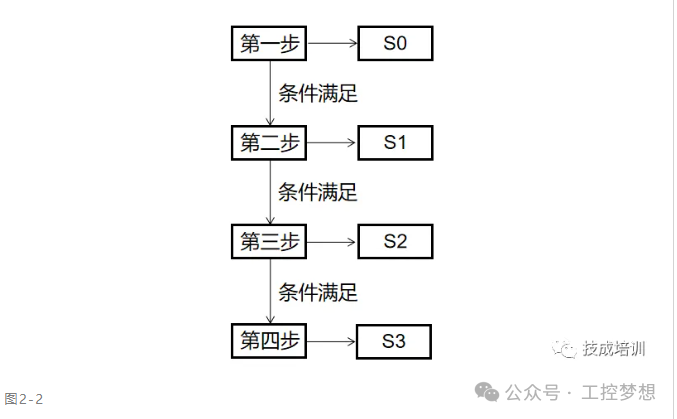
Figure 2-2: Schematic of Sequential Control Logic
3. Usage Specifications for STL and RET Instructions
-
STL (Step Ladder Diagram): Used to mark the beginning of a state step, e.g., STL S0 indicates entering state S0.
-
RET (Return): Must be placed at the end of the program, marking the end of the entire sequential control program.
-
Key Considerations:
-
Direct output coils must closely follow the STL instruction and cannot be placed arbitrarily.
-
When jumping state steps, the current step is automatically reset, but set instructions (SET) and cumulative registers will not be cleared.
-
Different state steps can reuse the same coil without conflict.
-
STL and RET Instruction Application Example: When programming state steps, strictly follow the principle of “drive the load first, then transfer the state” to avoid logical confusion.
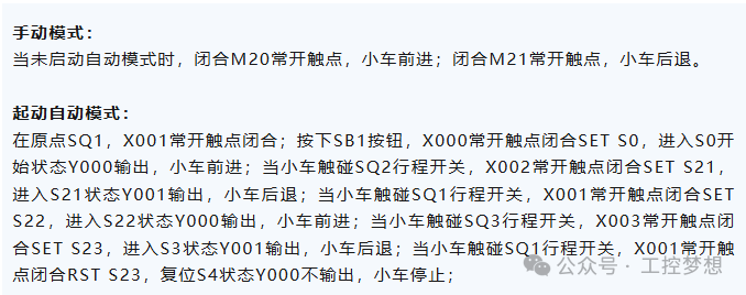
Figure 2-3: Schematic of STL and RET Instruction Programming Specifications
Implementation of the Task
1. I/O Address Allocation
According to the control requirements, input devices (buttons, limit switches) and output devices (contactors) need to be allocated corresponding PLC addresses:
Table
|
Input Points |
Comments |
Output Points |
Comments |
|---|---|---|---|
|
X0 |
SB1 Start Button |
Y0 |
KM0 Cart Forward Contactor |
|
X1 |
SQ1 Limit Switch 1 |
Y1 |
KM1 Cart Reverse Contactor |
|
X2 |
SQ2 Limit Switch 2 |
||
|
X3 |
SQ3 Limit Switch 3 |
2. Hardware Wiring Diagram
The wiring between the PLC and external devices must strictly follow electrical standards, with key points including:
-
Main Circuit: Live wire (L) and neutral wire (N) connected to the PLC power module.
-
Control Circuit: 24V DC power connected to the S/S common terminal.
-
Input Devices: One end of the normally open contacts of buttons and limit switches connects to X0~X3, and the other end connects to 0V.
-
Output Devices: Contactor coils controlled through PLC output terminals Y0, Y1.
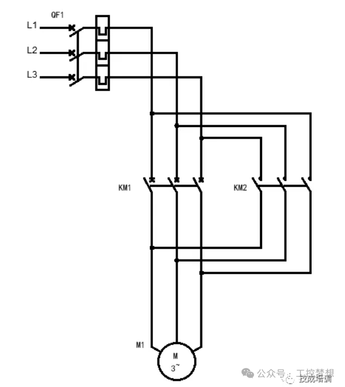
Figure 3-1: Schematic of PLC System Wiring
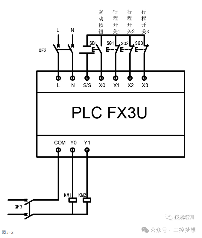
Figure 3-2: Schematic of Control Circuit Principles
3. Program Design
Using Step Ladder Diagram (STL) to design the sequential control program, the core steps are as follows:
State Step Division
S0 (Initial Standby) → S21 (First Forward) → S22 (First Backward) → S23 (Second Forward) → S24 (Second Backward)
Ladder Diagram Programming Key Points
-
State Activation: Activate the initial state using the SET S0 instruction.
-
State Transition: Use limit switch signals (e.g., X1 closed) to trigger SET S21 to enter the next step.
-
Timer Application: In state S22, connect T0 K300 (30 seconds delay) in series.
-
Program End: The final state is reset through RST S24 and executes the RET instruction.
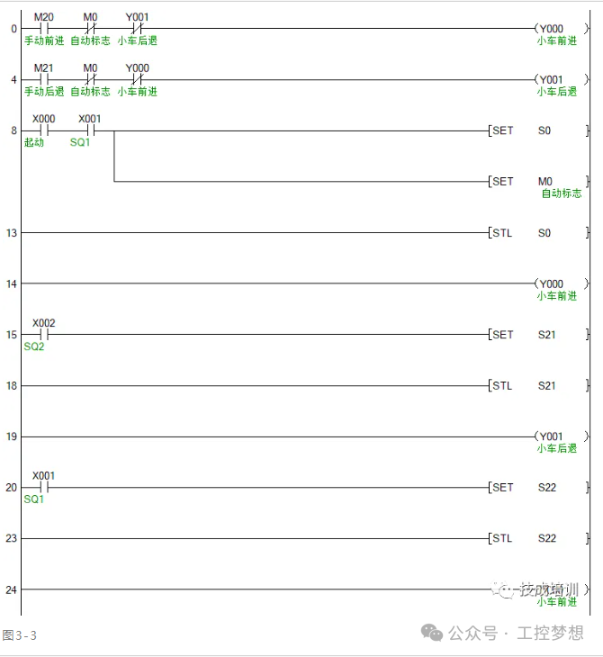
Figure 3-3: Ladder Diagram for Program Design
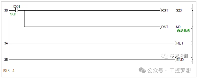
Figure 3-4: Ladder Diagram for State Reset
4. Program Debugging
Debugging is divided into manual mode and automatic mode, and it is recommended to verify step by step:
Manual Mode Testing
-
Short-circuit M20 contact → Verify Y0 output (cart forward).
-
Short-circuit M21 contact → Verify Y1 output (cart backward).
-
Check if all limit switch signals can trigger X1~X3 normally.
Automatic Mode Joint Debugging
-
Place the cart at SQ1 and press SB1 (X0 closed).
-
Observe the state transition sequence: S0→S21 (forward to SQ2)→S22 (backward to SQ1)→T0 delay→S23 (forward to SQ3)→S24 (backward to SQ1 stop).
-
Key checks:
-
Is the 30-second delay accurate (use GX Works2 to monitor the current value of T0)?
-
Does the state switch immediately when the limit switch is triggered?
Practical Skills Summary
-
State Step Numbering Norms: It is recommended to use S0S9 (initial step), S10S19 (manual steps), S20 and above (automatic steps) to avoid numbering confusion.
-
Interlock Protection Design: Connect the normally closed contacts of each other’s output circuits Y0 and Y1 in series to prevent the contactors from being energized simultaneously.
-
Fault Diagnosis Techniques: Determine the type of fault through the PLC indicator lights.
-
ERR light flashing: Program syntax error.
-
Input light not on: External wiring or sensor fault.
-
Output light on but no action: Contactor or power supply issue.
Conclusion
Through the material handling cart control case, we have fully practiced the PLC development process from requirements analysis → I/O allocation → program design → debugging optimization. This seemingly simple case contains the core idea of industrial control—using logic to control the physical world. Readers are encouraged to try expanding functionalities, such as adding emergency stop protection, fault alarms, or communication with the upper computer, to gradually enhance programming capabilities.
Remember, the essence of PLC programming is breaking down complex problems into executable steps, and sequential control is the most effective tool to achieve this goal. Open GX Works2 now and start writing your first industrial control program!
Previous Recommendations
The secrets that maintenance technicians won’t tell you: The principle and application of three-phase rectifier circuits.
Guide to using the Portal V18 simulator.
Siemens PLC S7 communication simulation tutorial: Achieving seamless data interaction with Portal.
PLC power outage data loss? 3 steps to set permanent saving of key parameters.
Weinview touch screen installment payment function setting tutorial.
Using Mitsubishi PLC to add an electronic lock to the touch screen.
Test if you are a real electrician or a fake electrician: If the current transformer passes through 5 loops, how to calculate the current?
Taichuan inverter TC600-2S0015G1 user manual.
Weinview touch screen OPC UA server communication configuration instructions.
How to use VBS scripts to automatically write WinCC7.5 data into Excel spreadsheets.
How to achieve Ethernet communication between MCGS PRO and S7-200 SMART.
How to design a vending machine that can give change using MCGS.
Weinview touch screen macro command conditional assignment usage instructions.
Has Kunlun Tongtai touch screen directly controlled the inverter?
How logical operations determine the fate of draft picks.
Technical insights | PLC custom countdown timer program design is actually that simple.
Two PLC implementation methods for motor delayed start and stop.
How to use PLC to control park fountains to achieve multiple timing logic.
Portal V19 installation tutorial: From beginner to expert, including common problem-solving and technical training benefits.