OVM6211 – Eye-Tracking Camera Features
Recently, I noticed that the VGA timing feels quite similar to modern MIPI. This timing or data transmission is really interesting.
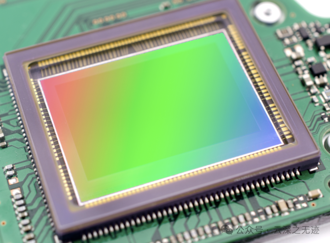
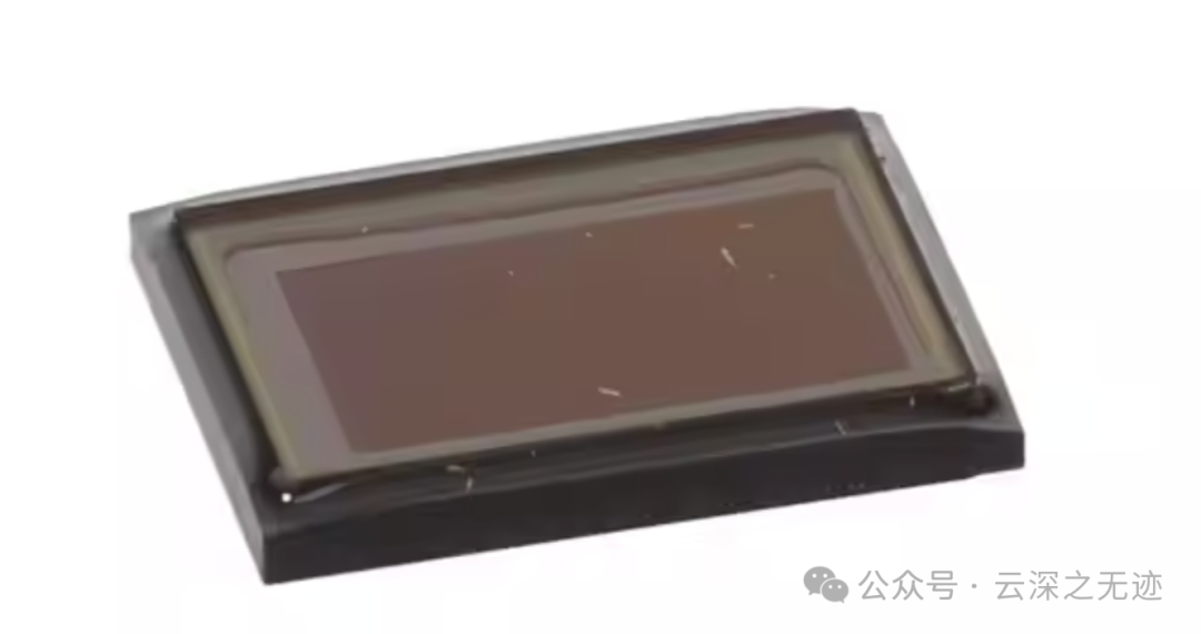
We see a large CMOS, with various types of optoelectronic PN junctions that I have discussed before.
Transimpedance amplifier design reference. Photodiode parameters like this.
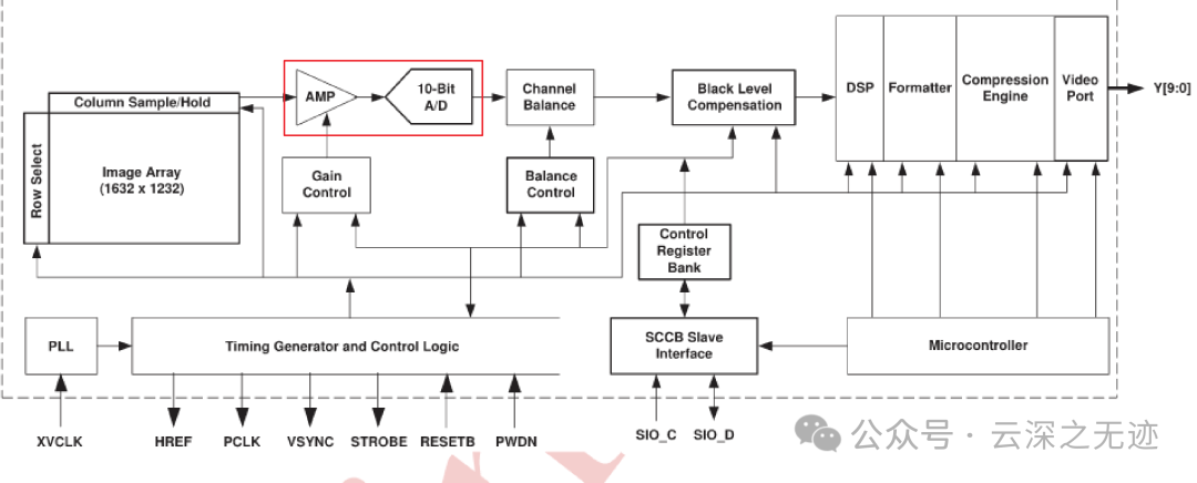
Since we are reading analog signals, there must be an ADC conversion module. Additionally, every time a photoconversion occurs, it must happen on a clock edge on the clock line.
As we can see, the lens is:
Optical data
OVM6211-RADA is suitable for eye-tracking and other human-machine interface systems, with a narrow field of view (FOV) of about 50 degrees.
The data sheet contains this section
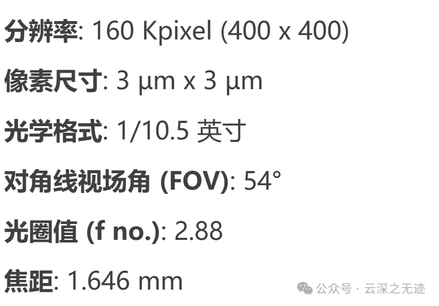
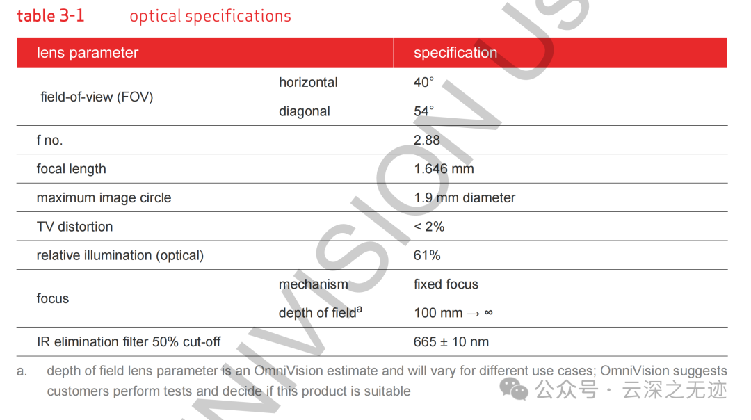
Field of View (FOV):
- Horizontal Field of View: 40°, indicating the horizontal viewing range of the image sensor.
- Diagonal Field of View: 54°, indicating the diagonal viewing range of the image sensor. It captures a wider scene, making it suitable for wide-angle shooting.
Aperture value (f no.): 2.88, indicating the size of the lens aperture. A lower aperture value means the lens can capture more light, which helps provide better image quality in low-light environments.
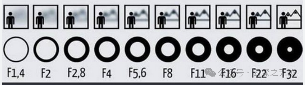
2.8 is a large aperture
Focal length: 1.646 mm, indicating the focal length of the lens. A shorter focal length is suitable for wide field of view applications, providing a larger depth of field and a wider shooting range.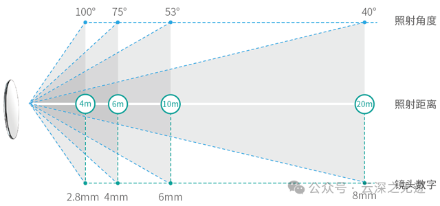 This 1.6m is quite short, allowing for a large range of capture since the eye-tracking is very close to the eye.Maximum Image Circle refers to the largest circular area formed by the lens on the image sensor. The diameter of this area is 1.9mm, indicating the range within which the lens can effectively provide clear images on the image sensor.TV distortion: less than 2%, indicating the degree of distortion at the edges of the image; distortion below 2% usually means relatively straight image edges.Relative illumination (optical): 61%, indicating the light distribution on the image sensor; a higher value usually means more uniform illumination provided by the lens.Focus mechanism: fixed focal length, indicating that the lens’s focal length cannot be adjusted, suitable for fixed scenes that require clear imaging.Depth of field: from 100 mm to infinity, the lens can maintain a clear range of distances, with a depth of field from 100mm to infinity means that this lens can remain clear over longer distances.IR filter 50% cut-off wavelength: 665±10 nm, indicating the filtering performance of the infrared filter; infrared light around 665 nm is effectively filtered.

There is also a 90° version
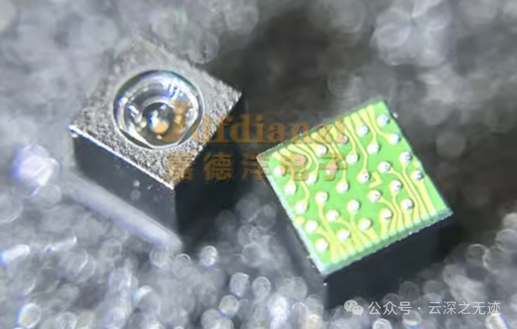
Because this thing is very small, sealing it at the back is not realistic, so the manufacturer sealed it directly.
This is what it looks like before sealing.
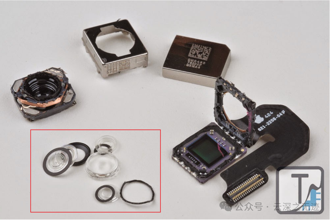
It is estimated that there are several lenses inside.
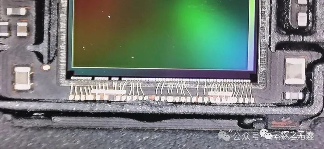
Previously, the CMOS of P30
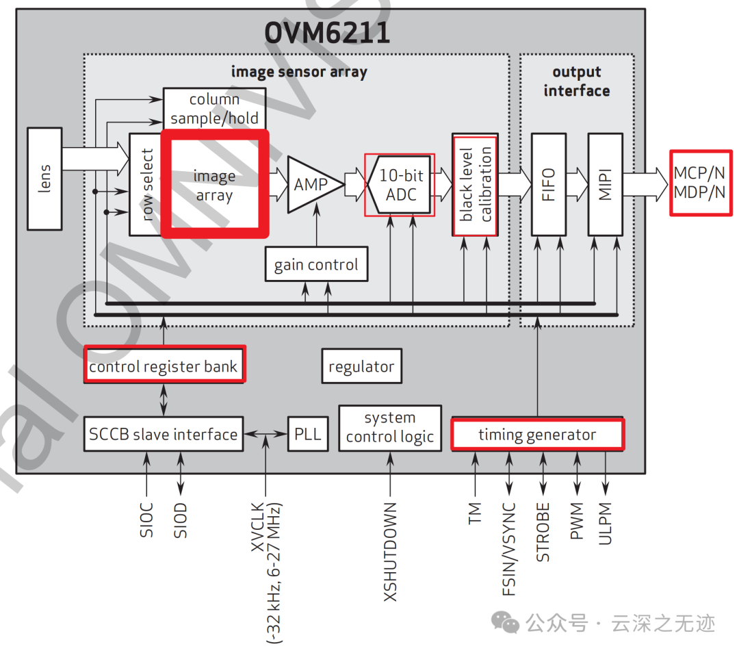
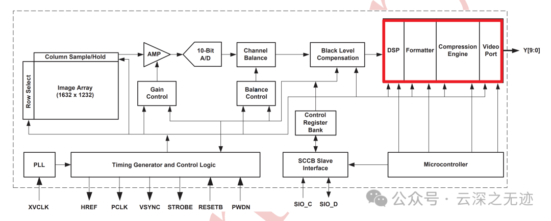
It is essentially a photosensitive array, and during sampling, it may also have a sample-and-hold circuit. Next, the AMP should be an aggregation module, converting it into a data stream; the front is a matrix, and the back is a data stream, suitable for the subsequent ADC conversion:
It feels like this
OV2640 is also available.
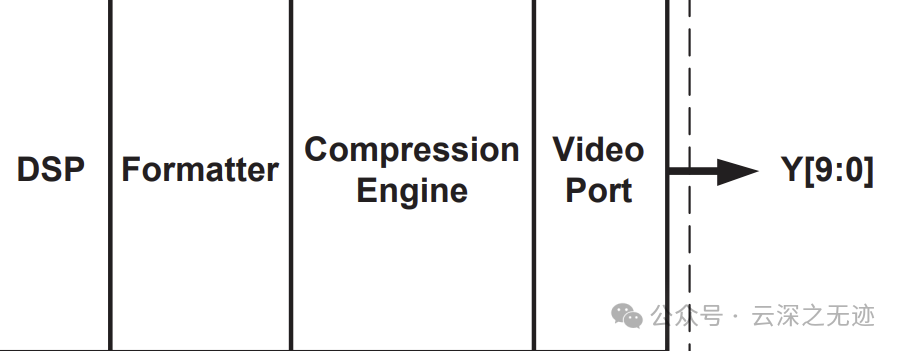
On the path of the AMP, gain control can be performed. Then it enters the ADC conversion module, followed by the next module, black level calibration. At this point, the image conversion is complete. The data stream is sent to FIFO to match the storage speed of the next level, and the MIPI module formats the data appropriately.
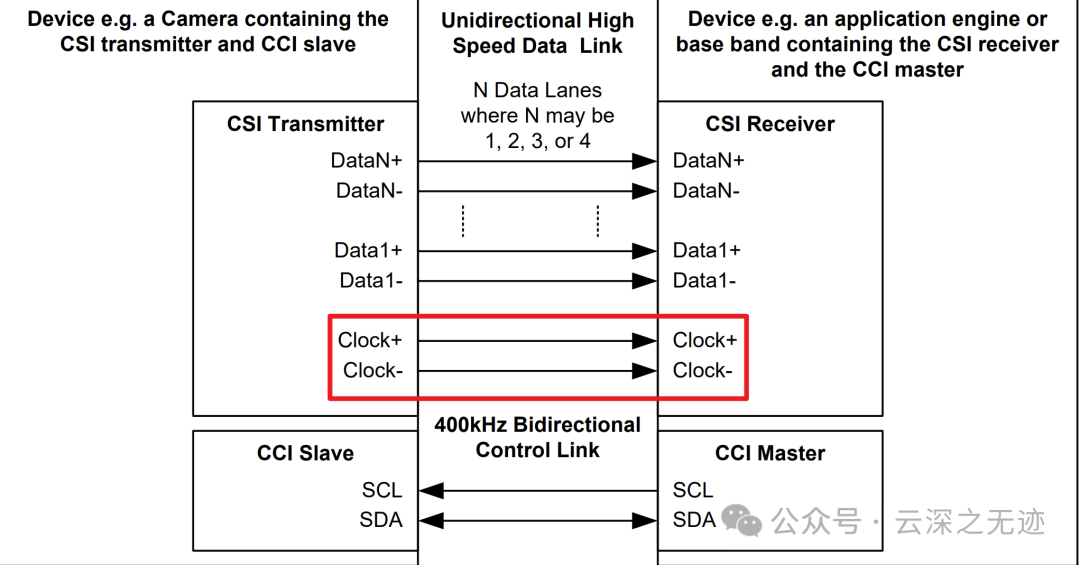
Single-channel MIPI serial output interface, with a maximum data rate of 600 Mbps.
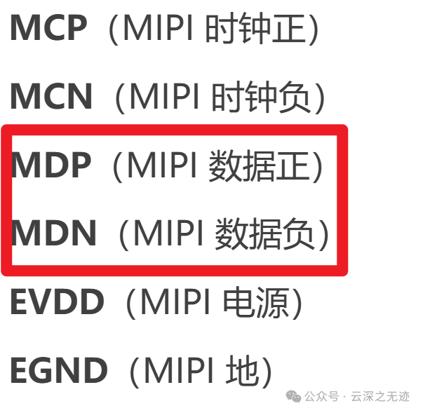
MIPI is a differential signal, with each pair being a signal line; a single channel means 2 signal lines.
IIC is used to control the registers, with MIPI outputting paired data.
MIPI interface sends long packets (image data) and short packets (frame synchronization signals).
Below are the register controls, connected to the IIC interface, which also requires a clock line because images require many different timing signals, so a clock generation module is also provided.
The above module is for serial output.
There is also a large category for parallel interfaces.
OK

This book contains a very good diagram
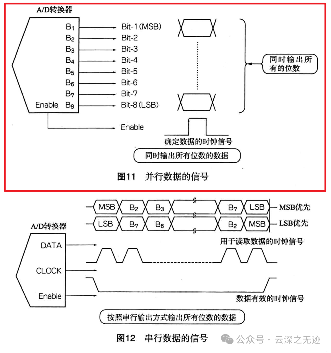
How parallel works and how serial works.
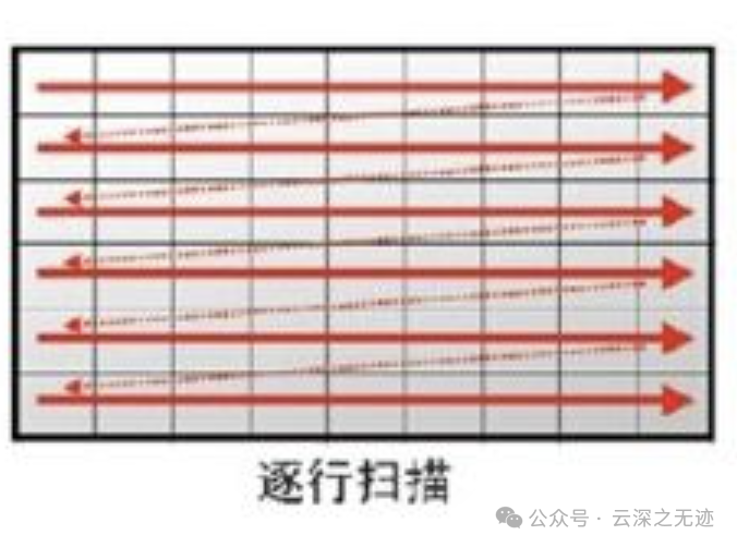
The camera’s scanning mode: progressive scan
Blurred
Each frame is composed of several horizontal scanning lines, with PAL having 625 lines/frame and NTSC having 525 lines/frame.
If all lines in a frame are scanned continuously from top to bottom, or if the scanning order is 1, 2, 3… lines, to achieve stable progressive scan images, each frame must scan an integer number of lines.
How should we understand this? A camera’s CMOS samples the light pixel points at single points.
An image looks like this
For example, a frame image is composed of 625 lines scanned continuously, scanning a total of 50 frames per second, which means a frame scanning frequency of 50 frames/second, or written as 50Hz, with a line scanning frequency of 31.25kHz.
This clock is equivalent to moving a pixel grid’s reference
The progressive scanning method requires high demands on the signal spectrum and the bandwidth of the channel transmitting that signal.
Next, let’s look at the output:

The actual pixel points are this many
Each pixel point has image data, and we continue to define how to describe the data at each point.
Essentially, this is the raw data, like 0101010101, unmodified data.
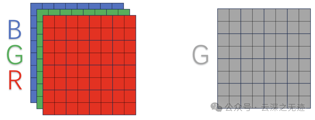
Image Sensor – RAW Format Analysis, thus RAW format means that the data of each pixel is output in N-bit binary.
For a sensor, we are interested in the pixel data at the pixel positions, but there are many ways to express an image; the camera we are using is in RAW format.
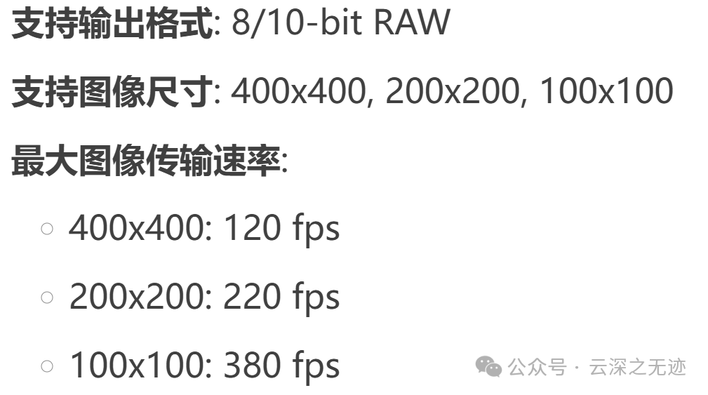
8-bit RAW: Each pixel’s data is output in 8-bit binary form. 1111111110-bit RAW: Each pixel’s data is output in 10-bit binary form.Next, let’s calculate the amount of data:
-
400×400 resolution, 10-bit RAW: Each frame image data volume is 400x400x10 bits = 1,600,000 bits = 200,000 bytes.
-
200×200 resolution, 8-bit RAW: Each frame image data volume is 200x200x8 bits = 320,000 bits = 40,000 bytes.
-
400×400: Full resolution output, suitable for applications requiring high resolution.
-
200×200: Reducing resolution through 2×2 merging or subsampling, suitable for scenarios requiring lower resolution and higher frame rates.
-
100×100: Further reducing resolution, suitable for scenarios requiring extremely low resolution and extremely high frame rates.
Here we encounter subsampling and merging:
2:1 and 4:1 monochrome subsampling: Reducing data volume by lowering resolution in the horizontal or vertical direction, suitable for scenarios requiring reduced bandwidth and processing load.
2×2 monochrome merging: Merging four adjacent pixels into one pixel, reducing resolution while increasing sensitivity, suitable for low-light environments.
Why are arrays so useful? (Using serial port host and client protocols), they all use bytes to measure data flow.
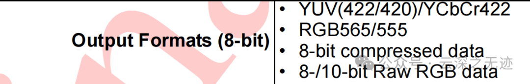
It can also output formats like YUV, RGB.
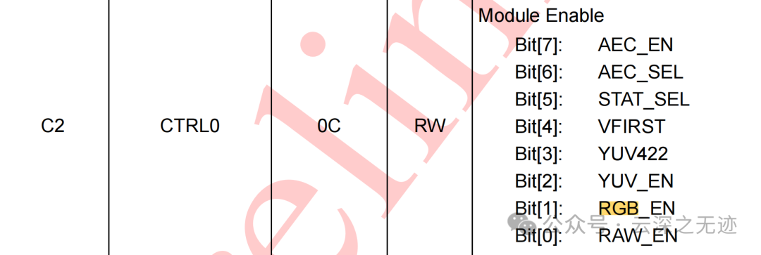
Configuration can be done using registers.
In simple terms, the output MIPI signal supports many data formats:
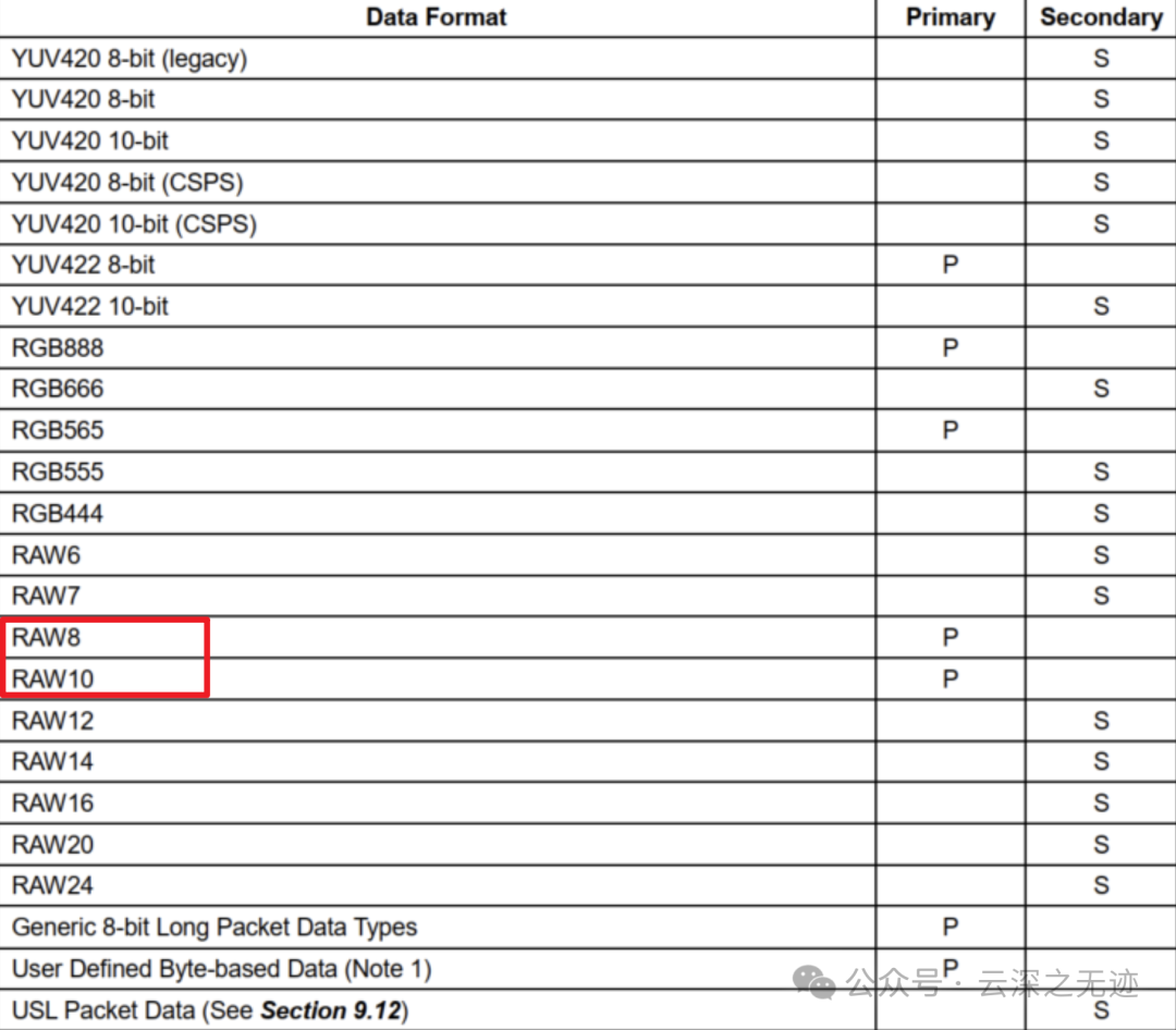
Primarily RGB, YUV, and RAW.
MIPI is an advanced protocol, and I cannot explain it in a simple and understandable way in one article. However, the protocol is layered, and you can learn the direction of data flow.
Also, it cannot be simulated; we use existing MIPI IP.
Always remember, the data flow is in bytes.
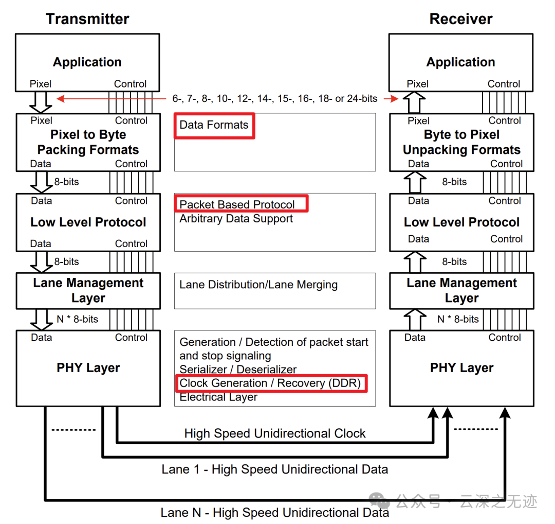
At the bottom is the data level conversion, then classifying these levels, and at the top is our application processing.
1. Physical Layer (PHY Layer): Uses differential signaling to transmit data. Supports low-power mode (LP Mode) and high-speed mode (HS Mode).2. Protocol Layer (Protocol Layer): Defines the format and transmission rules of data packets. Includes long packets (Long Packet) and short packets (Short Packet).3. Application Layer (Application Layer): Defines the format and content of image data. Supports various pixel formats (such as RAW10, RAW12, YUV422, etc.).
Due to the large and complex data volume, some frames are modified. MIPI CSI-2 data packets are divided into long packets and short packets.
Long packets are used to transmit image data, formatted as follows:
- Packet Header:
- Data Identifier (DI): Data type identifier (such as RAW10, YUV422).
- Word Count (WC): The number of words in the data packet (16 bits).
- ECC: Error check code (8 bits).
- Payload:
- Image data (such as pixel values).
- Packet Footer:
- CRC: Cyclic Redundancy Check code (16 bits).
Short packets are used to transmit control information, formatted as follows:
- Packet Header:
- Data Identifier (DI): Data type identifier (such as frame start, frame end).
- Word Count (WC): Fixed at 0.
- ECC: Error check code (8 bits).
- Payload:
- Control information (such as frame number, line number).
Please make sure to read the next article. I will write about the most basic VGA timing and then transition to MIPI timing.