A few years ago, I planned to use a Raspberry Pi to build a small robot, but when I actually started working on it, I found that using someone else’s designed board was not very convenient.
On one hand, the Raspberry Pi is designed for a wide range of users, which limits customization; the shape, size, and peripheral configurations of the board do not meet ideal requirements. On the other hand, the performance of the Raspberry Pi is relatively… concerning, as the cost is a factor. To popularize this card computer, it cannot use an overly expensive SoC (the Broadcom CPU on the Raspberry Pi is specially supplied).
Therefore, to satisfy my personal obsession and to learn about high-speed PCB design and manufacturing, I decided to design my own ARM core board and get started!
Board Fabrication Process:(Scroll to the end to view the complete demonstration video)
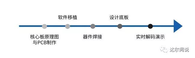
Step 1: Schematic Design and PCB Fabrication
The board uses a Allwinner Cortex A53 quad-core CPU, 1.5GHz clock speed, six-layer DDR3 memory, and mini-PCIE size, which should completely outperform the Raspberry Pi. The entire board exposes pins for SPI, IIC, UART, etc. Later, I will also create an Arduino-compatible baseboard. Once the board is processed, I will port uboot and the Linux kernel, which should be the smallest Linux development board to date.
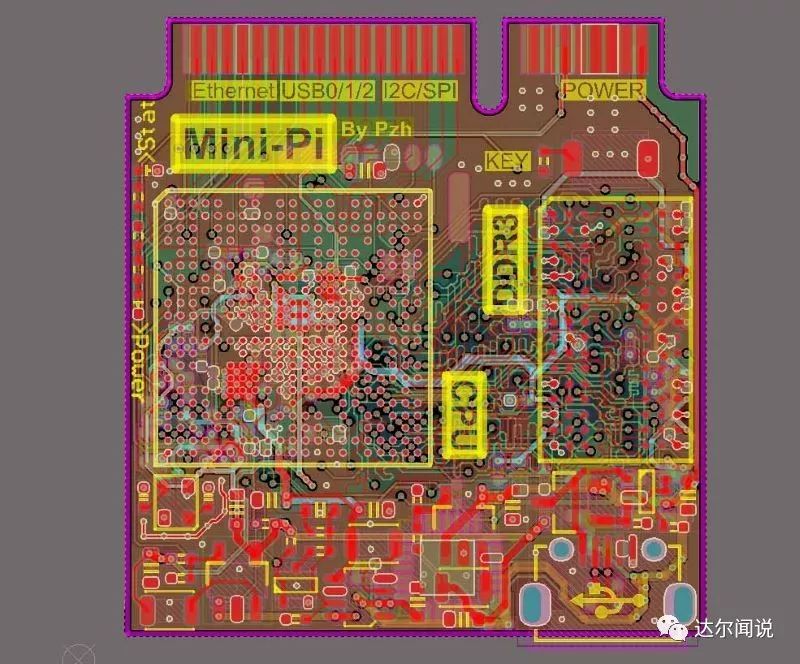
Complaints: PCB fabrication is difficult! Finding a suitable manufacturer to prototype such a multi-layer precision PCB (not in bulk) is really not easy. I searched extensively on Taobao for PCB prototyping manufacturers, but none could handle 0.3mm pitch BGA boards. I heard that Jialichuang could prototype, so I sent the board there to try. The first review passed, but when preparing for processing, I received a call saying: “We cannot make your board; the 0.2mm vias exceed the process limits, and even if you pay extra, we cannot do it!” Fortunately, I eventually found a manufacturer that could do it, although the price was quite high.
Step 2: Soldering Components
Since this was my first time hand-soldering BGA chips, especially with a 0.3mm pitch BGA, I initially had no confidence.
Generally, BGA soldering is done by manufacturers because it requires specialized reflow soldering equipment that can precisely control the temperature curve. It is impossible to use such professional equipment in a personal dormitory, so I had to showcase my actual skills.
Based on various experiences with BGA soldering, first, apply solder balls to the chip, which involves aligning a stencil with the solder pads and sprinkling solder balls (which can be easily purchased online, available in various sizes, usually counted in thousands) onto the chip, then heating to melt the solder. This way, the solder balls on the chip become the connections between the PCB and the chip, which is the meaning of BGA (Ball Grid Array).
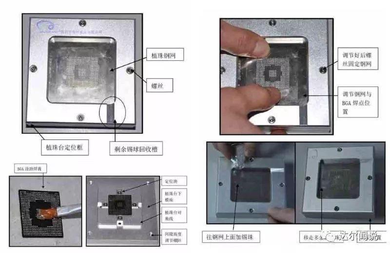
Specific operation for applying solder balls
The CPU and DDR chips I purchased are brand new, so they already have solder balls applied from the factory, which saves this step. However, if the first soldering attempt fails and needs to be reworked, it will still require reapplying solder. My soldering equipment is as follows:
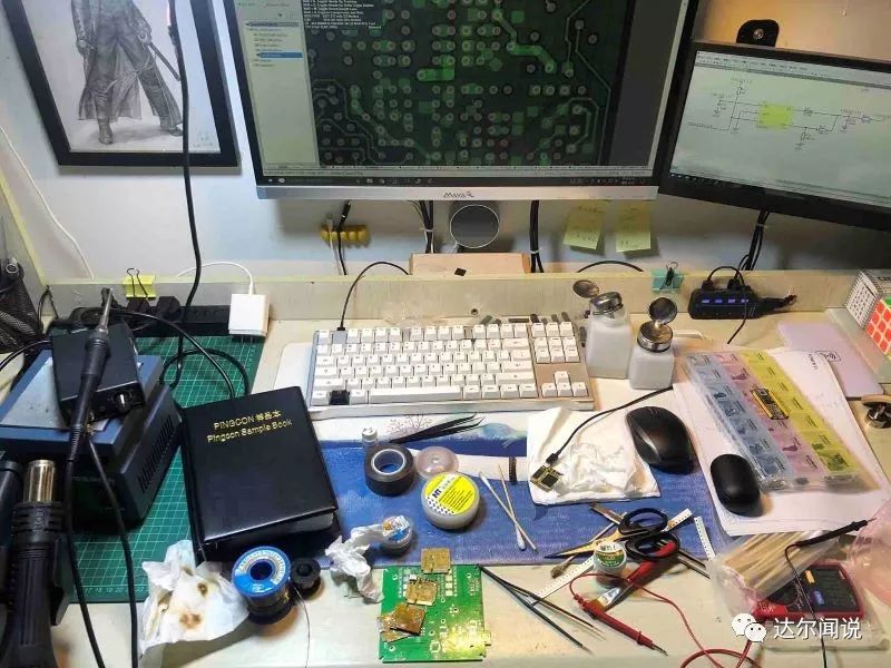
The soldering method I used was: first solder all components except the BGA (mainly the power circuit and some peripherals), then power on to test the voltages (5V, 3.3V, 1.2V, CPUX’s 1.3/1.4V) to see if they are normal. If they are normal, it indicates that the board is halfway successful, as the PCB processing should at least be fine (although the PCB will undergo flying probe testing before shipment, which only guarantees connectivity; shorts are difficult to check).
Fortunately, I found no issues with this board, which further indicates that my routing and rule settings are okay.
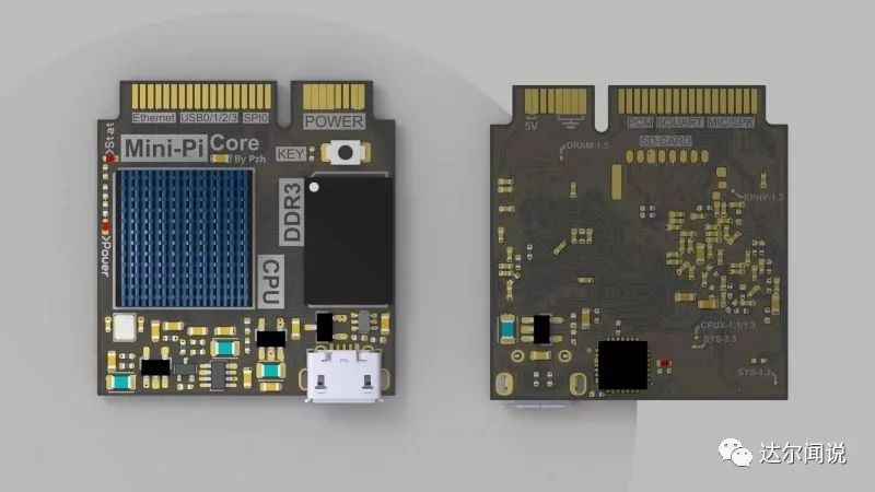
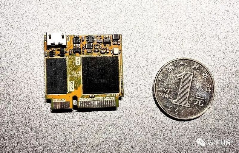
Back of the core board
After soldering the power and peripheral components, the most important CPU and DDR were soldered, which was also the step I was least confident about.The BGA pins are completely distributed under the chip, so they are not visible to the naked eye. Therefore, when designing the PCB, it is essential to accurately print the chip boundary silk screen, which serves as the only standard for aligning the chip. After aligning the chip, use a hot air gun to heat it at the lowest wind speed, 250°C. (Note that the nozzle should be removed to allow for even heating through a larger outlet.) After blowing for about a minute, you can see the chip slightly repositioning. At this point, carefully touch the chip with tweezers; if it self-centers, it indicates that it is basically soldered well.
Due to my lack of skill in hot air soldering, I ruined two boards (the reason was that the temperature was too high and the blowing was too long, causing the pads to come off). However, I ultimately succeeded in soldering one board. With this experience, I feel that the next time I solder a BGA, it should be much easier.
Appearance of the soldered chip
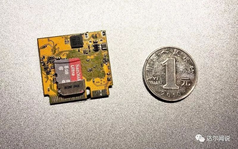
After inserting the SD card and powering on via USB, even before connecting via SSH, I could already see the status LED blinking, indicating that the CPU started normally! Thus, my first ARM core board hardware can be considered a complete success.
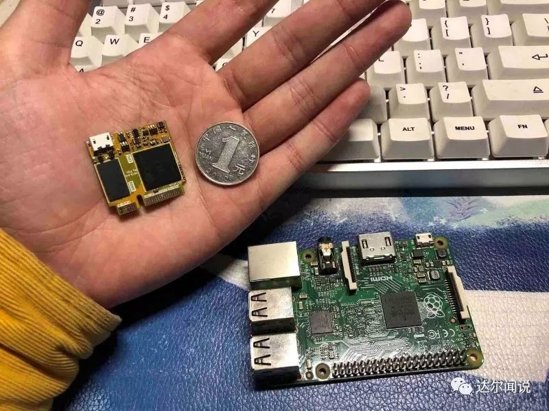
My board with a coin and a Raspberry Pi
Step 3: Software Porting
After ensuring the hardware works correctly, it is time to proceed with software porting. The porting and compilation of U-BOOT and the Linux kernel were mostly completed while waiting for the PCB to be processed. After writing the system to the SD card and inserting it into the board, powering on successfully entered the kernel. The file system used is Ubuntu 16.04, which is the best choice in the Debian family and is basically fully compatible with the Raspberry Pi. The following image shows the effect of logging in via SSH through the onboard USB serial port 👇
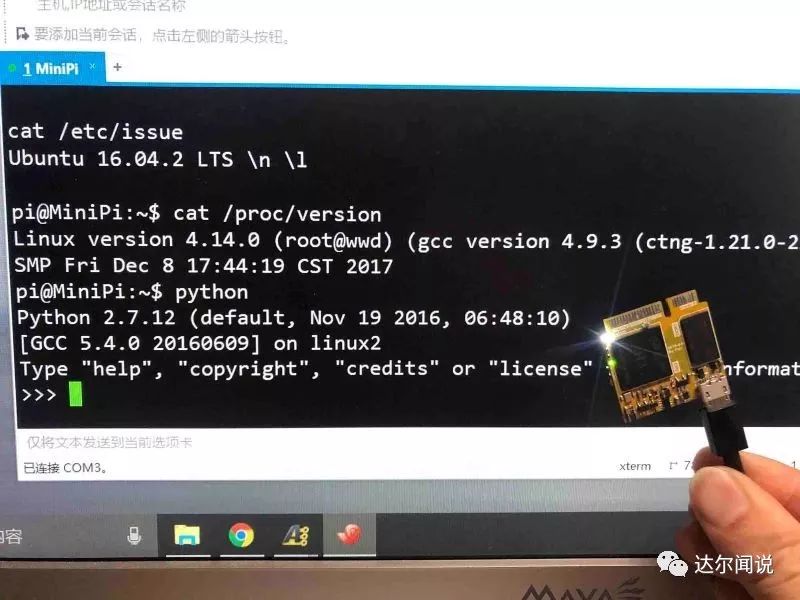
SSH login effect
Step 4: Baseboard Design
After confirming that the core board is fine, I quickly designed a baseboard to expose resources such as USB, Ethernet, SPI, IIC, etc. At the same time, the baseboard integrates an Arduino Micro (Mega32U4), which communicates with the CPU via serial or IIC (in fact, the core board can directly run the Linux version of the Arduino IDE to download programs to the baseboard’s Arduino).
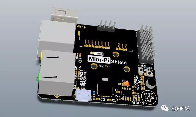
The baseboard mainly exposes all IO resources from the core board through the mini-PCIE base, such as USB ports, Ethernet ports, I2C, SPI, serial ports, microphones, speakers, etc. The functionality is relatively simple, requiring only two layers for routing, with all components placed on the same layer to simplify soldering.
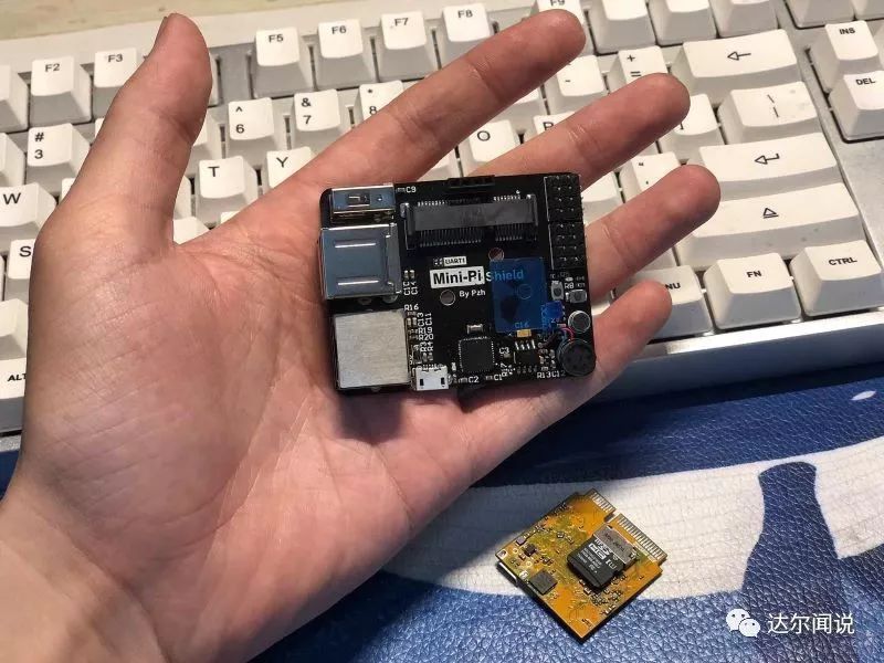
Finished baseboard
At the same time, the baseboard also has an onboard Mega32U4 chip. After burning the Arduino Micro’s Bootloader, it can be used as an Arduino, with both serial and I2C interfaces connected to the core board for communication. Of course, the core board can also directly compile programs to download to the Arduino.
Finally, comparing the size of the finished board with the Raspberry Pi, it is about half the size and has many more peripherals:
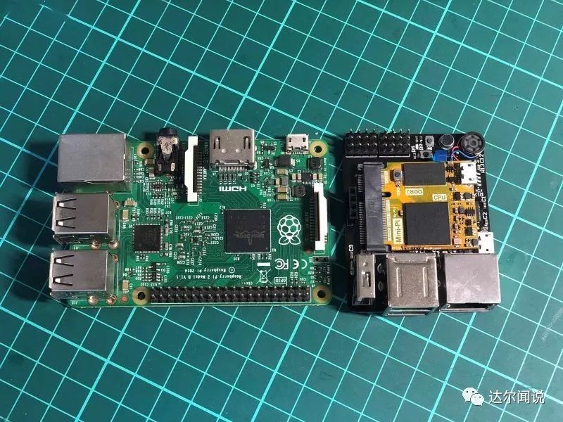
My board compared to the Raspberry Pi
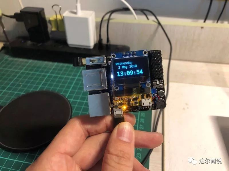
Since most Linux systems are accessed via SSH or remote desktop, the baseboard does not expose an HDMI interface (another reason is to disable the GPU to reduce power consumption and heat). Therefore, it is best to have a small onboard screen to display some information, such as CPU usage, temperature, IP address, etc. Here, I chose a commonly used OLED12864 screen, which is compact and displays beautifully. It is driven via I2C, and the wiring is quite simple, plug and play.
Step 5: Real-time Decoding Demonstration
What is the difference between driving an OLED with Linux and driving an OLED with a microcontroller (like Arduino)? First, Linux is a complete desktop-level operating system, and many algorithms (like image processing, network applications) can be directly ported and run. Therefore, there will be no resource scarcity like on microcontrollers, where displaying an image or even a piece of Chinese text requires pre-preparation with PC software, storing it in the microcontroller’s flash, and then downloading and running it (because this Linux board is essentially a computer, haha). Secondly, Linux supports multitasking, which means it can easily combine OLED display with other applications, making the screen a great tool for displaying content. For example, the following video demonstrates how to decode a video (the famous Bad Apple) in real-time and play it on the OLED after image processing:
Additionally, it is possible to integrate Intel’s Movidius chip’s BSP onto the board, allowing for neural network acceleration. It is entirely feasible to port several neural network algorithms to design a mini AI robot. Integrating the Movidius chip onto the board does carry some risks, but using Intel’s Neural Compute Stick 2 (NCS2) is more convenient, reducing the design process and error rate.
Every attempt yields rewards—N firsts led to the success of this board
The first time designing a high-speed multi-layer ARM board was successful, which is quite lucky (of course, I had been researching various materials intermittently for several months beforehand). Reflecting on the entire design process, there were many uncertainties.
The first time conducting multi-layer board design, and directly going for 6 layers.
The first time designing the ARM core board circuit: needing to consider complex power systems, PCB impedance calculations, signal length routing, EMC optimization, etc.
The first time processing a multi-layer precision PCB: 6 layers, 3mil line spacing, 0.2mm vias, and the price was more than 20 times that of a 2-layer board, and even after processing, it was uncertain whether it would work.
The first time hand-soldering BGA: even if the PCB is fine, soldering is a significant issue. Once soldering is complete, if the board does not work, it is challenging to troubleshoot the cause.
Fortunately, all the above issues were perfectly answered with the LED on the board lighting up.
This article was provided by the contributor Zhi Hui (personal website: www.pengzhihui.xyz) and compiled and formatted by Ni Jie.

Contributor Zhi Hui Series—I am Zhi Hui, a regular contributor to “Darwen Says”, sharing cutting-edge knowledge in artificial intelligence from time to time.
 Follow “Darwen Says”
Zhi Hui’s previous reviews:
-
Should beginners use microcontrollers or Raspberry Pi for embedded hardware?

 Click the original text to view the complete video of NCS2