
1. MIPI
1.1 Introduction to MIPI
What is MIPI?MIPI: Mobile Industry Processor Interface.It is an open standard and specification initiated by companies such as Intel, Motorola, Nokia, NXP, Samsung, STMicroelectronics, and Texas Instruments, aimed at addressing the high bandwidth requirements for HD image transmission in mobile application processors while resolving the conflict with the low speed of traditional interfaces. It provides a unified industry standard, shortens product development cycles, and enhances compatibility among products from different manufacturers.Its core features include: low power consumption, high bandwidth, anti-interference capability, and a modular architecture.
Currently, MIPI Alliance members include: Intel, Qualcomm, Nokia, AMD, ARM, MediaTek, Cadence, Synopsys, Sony, Siemens, Sony Ericsson, Toshiba, Philips, and Zhongxing Micro, among others.
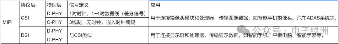
1.2 MIPI Protocol Layers
MIPI CSI (Camera Serial Interface): Defines the serial interface protocol between the camera module and the processor for transmitting image and video data.
MIPI DSI (Display Serial Interface): Defines the serial interface protocol between the processor and the display for transmitting display data.
Thus, the MIPI camera interface is called CSI, and the MIPI display interface is called DSI.
1.3 MIPI Physical Layer
MIPI D-PHY (Digital Physical Layer): A physical layer protocol for high-speed serial interfaces, primarily used for high-speed data transmission between cameras and displays, characterized by low power consumption and strong anti-interference capability.
MIPI C-PHY (Camera Physical Layer): Another physical layer protocol suitable for high bandwidth applications, such as high-resolution cameras and displays, using three-wire differential signal transmission.
1.3.1 MIPI Physical Layer D-PHY
D-PHY signals include high-speed mode (HS mode) and low-power mode (LP mode). In high-speed mode, data signals are transmitted differentially, with a signal swing of about 200mV, supporting data rates of up to 4.5Gbps. In low-power mode, the signal switches to single-ended mode, with a signal swing of 1.2V and a maximum rate of 10Mbps.
The MIPI CSI D-PHY camera has three power supplies: VDDIO (IO power), AVDD (analog power), and DVDD (core digital power).
Different sensor module cameras have different power supply requirements, with AVDD analog voltage typically at 2.8V (designed with a high PSRR LDO).
VDDIO voltage should match the level of the MIPI signal lines, generally at 1.8V.
DVDD is usually 1.5V or 1.2V, which may be provided internally by the sensor chip (with internal VDDIO 1.8V converting to 1.5V or 1.2V) or supplied externally.
D-PHY Layout: Differential impedance of 100Ω±10%, with inter-pair length matching requirements of less than 100mil and intra-pair length matching requirements of less than 10mil, avoiding cross-layer segmentation.
1.3.2 MIPI Physical Layer C-PHY
C-PHY does not have a separate clock signal; the clock is embedded in the timing of the communication. In the C-PHY architecture, data is transmitted through three different phase differential signal pairs, a mechanism known as “three-phase transmission.” This transmission method has a higher symbol rate and greater spectral efficiency than traditional two-phase differential signal transmission.
Each lane consists of three data lines, which are differentially paired. Three-wire length matching (deviation ≤10mil), with impedance controlled at 50Ω (single-ended).
1.4 Summary of MIPI
The C-PHY and D-PHY of the chip can be designed to be compatible, such as the MIPI interface of Rockchip’s RK3588, which can be configured with either a D-PHY or a C-PHY interface.
2. DVP Interface Cameras
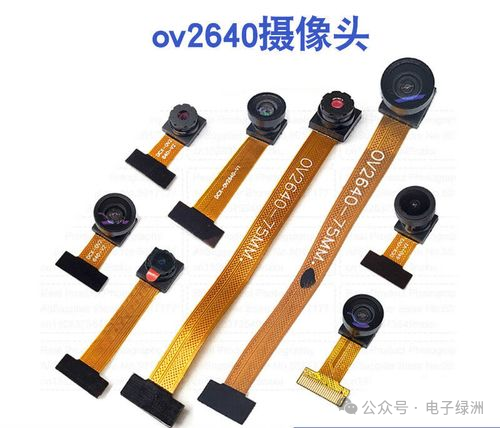
DVP Interface Camera Module
DVP: Digital Video Port, is a parallel transmission interface, which is slower and has lower bandwidth.
Corresponding signal pins:
PCLK: Sensor output clock, pixel clock signal.
MCLK (XCLK): External clock input for the sensor, typically at a frequency of 24MHz or 27MHz.
VSYNC: Frame synchronization signal; one signal per frame, with a frequency of several tens of Hz (30Hz).
HSYNC: Line synchronization signal; (frequency of several tens of kHz).
D[0:11]: Parallel data (can be 8/10/12 bit data width).
500W can still barely use DVP, while 800W and above generally use MIPI interfaces.

——END——
In the jungle society, tears are never believed; no amount of complaints will help, and no one will pity you.
Recommended Reading
Differences between Lithium-Ion and Lithium-Polymer Batteries
Hardware Learning: Components – Buzzers
Can Schottky Diodes be Used in Parallel?
Single Power Supply Solution for Differential Audio to Single-Ended Audio
Lithium Battery Protection Scheme: DW01A + 8205 Battery Protection Board Design
Relationship between MOSFET Threshold Voltage Vgs(th) and Temperature: Discussion on Negative Temperature Coefficient
Like, Share, and RevisitThank you for your “three consecutive supports”Limited-time free QR code to join the group for more technical and industry information exchange