▲ Click ☆ to star me, in case of losing contact
Project Introduction
This trial project is based on the NXP S32K312 series core board, aiming to collect the analog signal from a potentiometer using the ADC (Analog-to-Digital Converter) to control the duty cycle of PWM (Pulse Width Modulation), thereby achieving the manual dimming function of a small desk lamp. The main goal of the project is to utilize the powerful peripheral functions of the S32K312 chip, combined with the ADC and PWM modules, to implement a simple manual dimming system. By manually adjusting the position of the potentiometer, the ADC converts the analog signal into a digital signal, which in turn adjusts the PWM duty cycle to control the brightness of the LED lamp, achieving the effect of manual dimming.
Trial Project Process Record
1. Development Environment Setup
First, I set up the development environment for S32K312 according to the tutorial provided by the DadaTong platform. I installed S32 Design Studio for S32 Platform (version 6) and configured the S32K3xx development package and RTD driver. The setup process was relatively smooth, and the documentation and tutorials provided by NXP were very detailed, helping me quickly complete the environment configuration. Those who are unfamiliar can refer to the author’s first blog post.
2. Hardware Connection
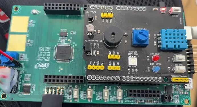
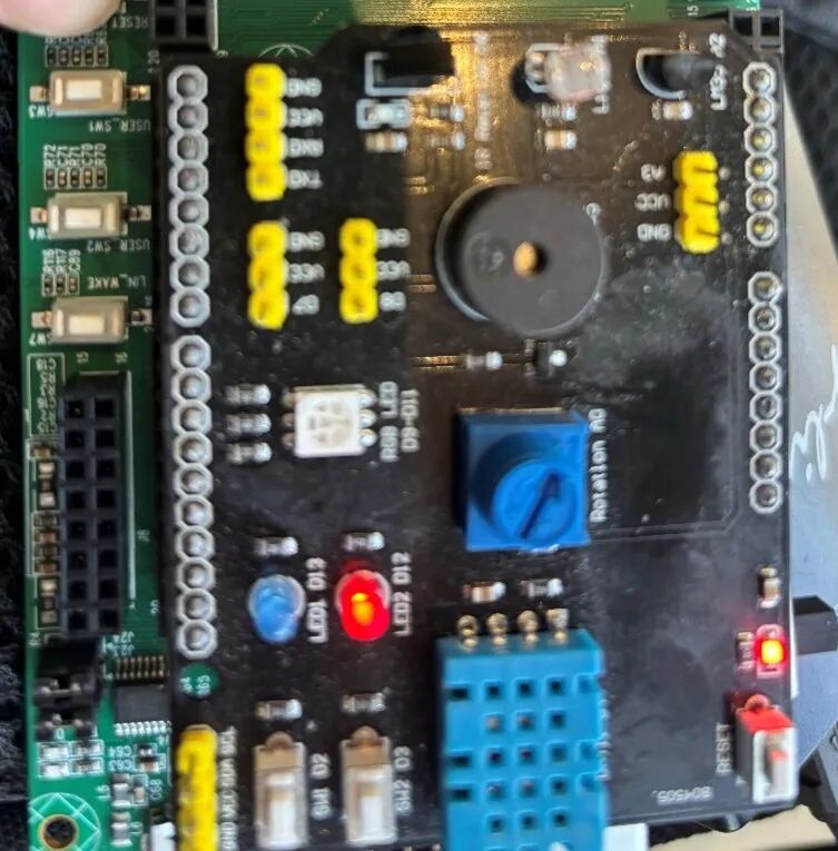
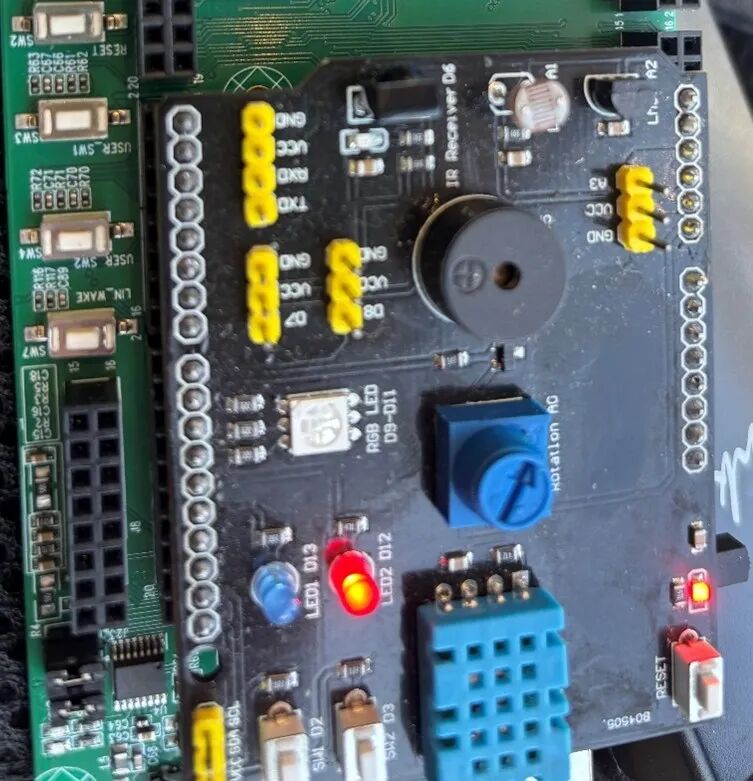
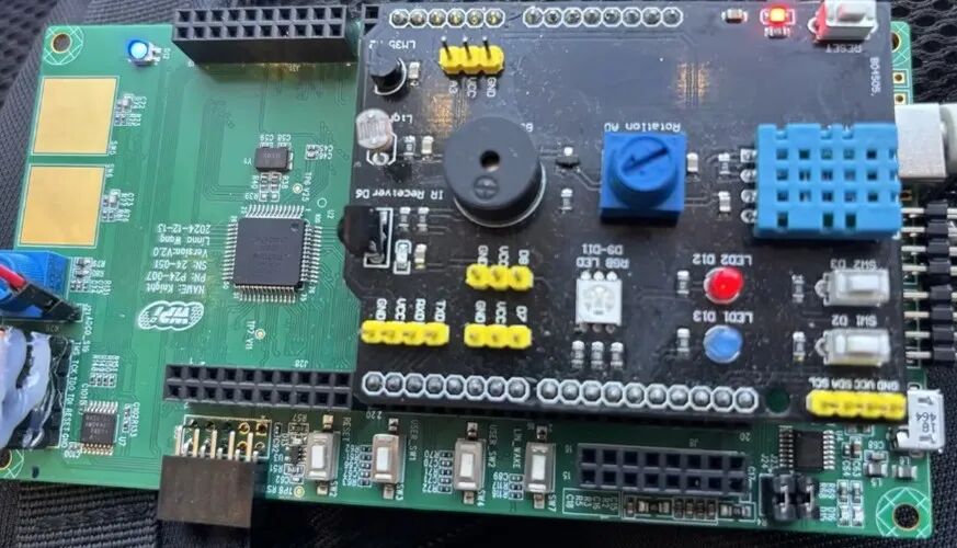
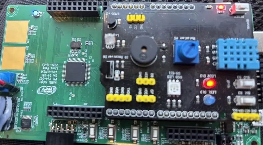
A ready-made Arduino expansion board was used here, which has various peripherals on board to meet the needs of this experiment. The physical image is shown below.
3. PWM Peripheral Configuration
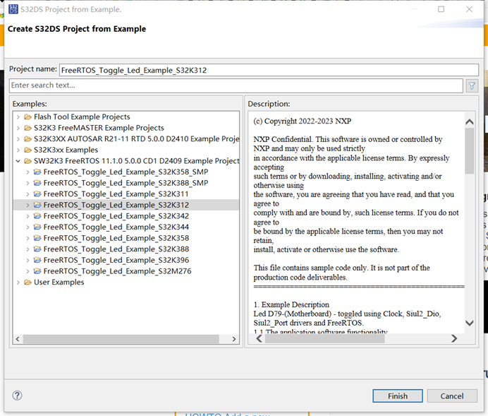
First, we create a FreeRTOS demo project.
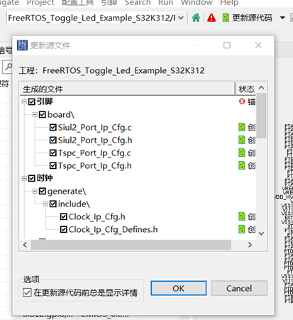
Before the first compilation, remember to update the source code.
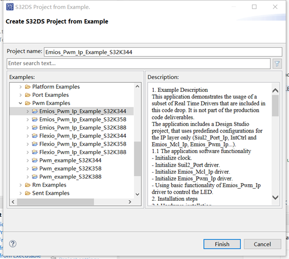
Refer to the example Emios_Pwm_Ip_Example_S32K344 code to configure the PWM peripheral of S32K312.
We use pin D12 to control the LED, as shown in the schematic, D12 is connected to the development board PTB15.
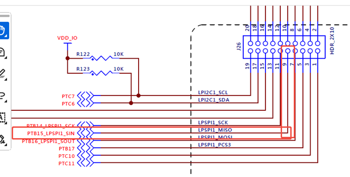
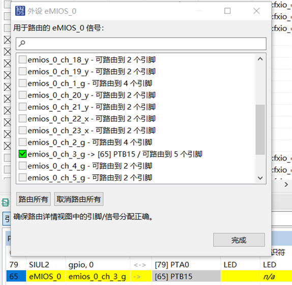
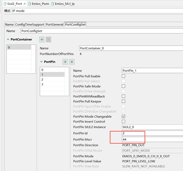
First, we configure PTB15.
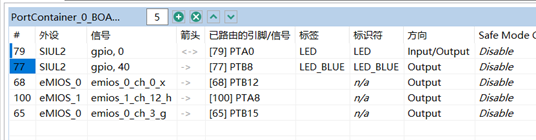
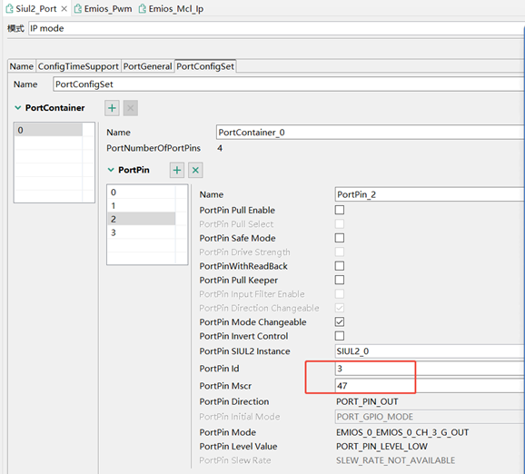
Then configure the remaining pins.
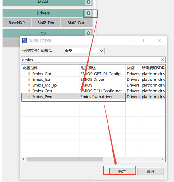
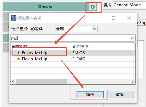
Further add components Emios_Pwm and Emios_Mcl_Ip.
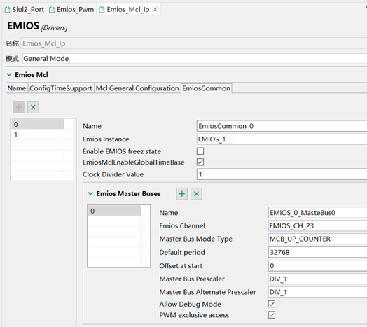
Configure Emios_Mcl_Ip.
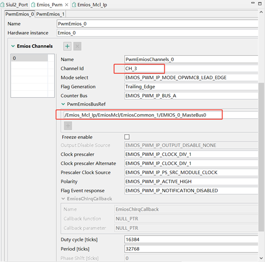
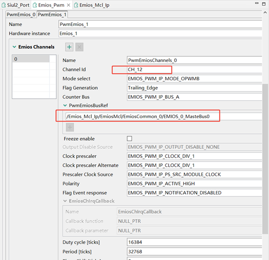
Configure Emios_Pwm.
Configure Siul2_Port.

Next, modify the main.c code file.
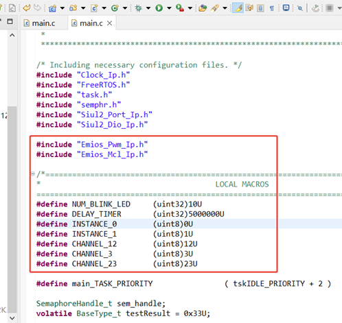
Add header files and macro definitions.
Add module initialization code.
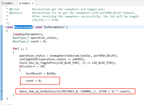
Add PWM control related code in the ReceiveTask thread.
Compile and run, and you can observe that the red LED connected to the Arduino expansion board D12 increases in brightness every second, and after about ten seconds, it will automatically turn off and then increase brightness again.
Effect Image:
Low Brightness
High Brightness
4. ADC Configuration
The configuration method for the ADC module can refer to the author’s third blog post.
You can also refer to the following link:
https://blog.csdn.net/lnniyunlong99/article/details/136059070
This time, we use PA0 on the Arduino expansion board to read data from the potentiometer. By checking the schematic, we know that PA0 of the Arduino expansion board is connected to the chip’s PTD1 pin.

First, we add the pin configuration for PTD1.

Add the ADC driver component.

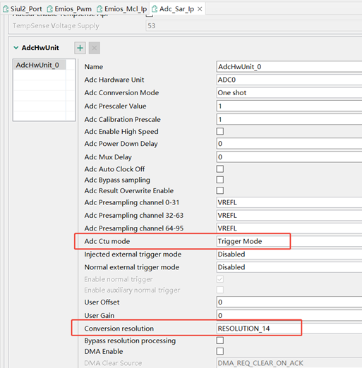
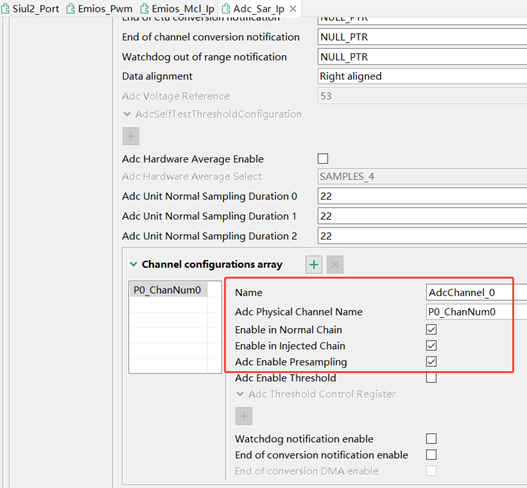
Configure the ADC component.
Next, modify the code section, edit the main.c file.
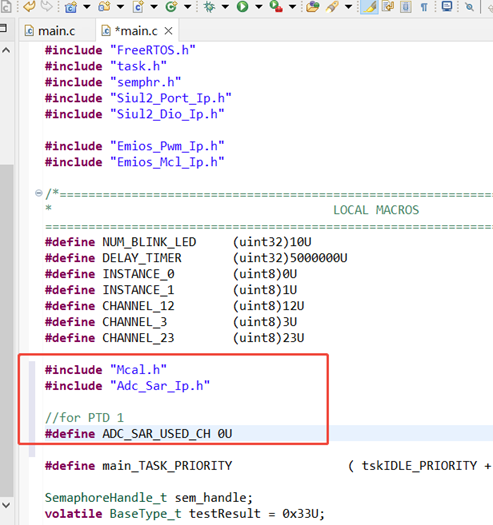
Add new header files and macro definitions.
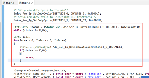
Add ADC initialization code.
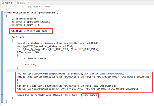
Modify the code in the ReceiveTask thread.
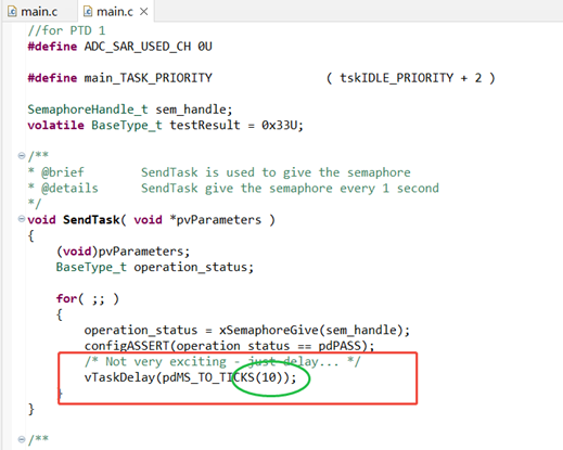
Finally, to increase the ADC sampling frequency, you need to modify the parameters of the vTaskDelay function in the SendTask thread.
If debugging does not work properly, you need to adjust the debugger-related configuration.
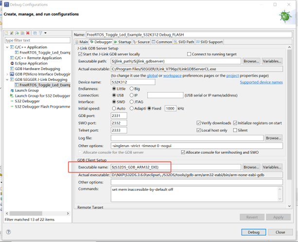
The project configuration is now complete.
Results Display
ADC Reading
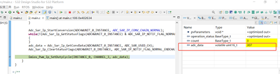
LED Lighting Effect
ADC Reading
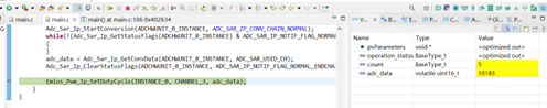
LED Lighting Effect
User Experience and Insights
Through this trial of the S32K312 development board, I gained a deeper understanding of NXP’s S32K3 series chips. The S32K312 chip has rich peripheral resources, especially the performance of the ADC and PWM modules, which can meet complex control requirements. During the development process, S32 Design Studio provided a good development environment, and with NXP’s RTD driver and HAL library, it greatly simplified the configuration and control of peripherals.
During the project development process, I encountered some challenges, such as adjusting the ADC sampling accuracy and setting the PWM frequency. By consulting NXP’s official documentation and community forums, I gradually solved these problems and accumulated valuable experience. In addition, using Git for code version management helped me quickly revert to previous versions during debugging, avoiding the hassle of reconfiguration.
Overall, the S32K312 development board is very suitable for development in automotive electronics and industrial control fields, especially in application scenarios that require high-performance ADC and PWM. Through this trial, I not only mastered the basic usage of the S32K312 but also accumulated rich debugging experience, laying a solid foundation for future project development.
The latest examples from S32DS are not adapted for S32K312, only for S32K344 and other chips. Although they cannot be directly compiled and programmed, they are still very helpful for us beginners to configure the relevant functions of the S32K312 chip. With a little thought, I believe the peripherals of the S32K312 can also be driven and used normally.
Future Outlook
In future projects, I plan to further optimize the dimming algorithm, add more sensors and control logic, and achieve a more intelligent lighting system. At the same time, I also look forward to exploring other peripheral functions of the S32K312 chip, such as CAN bus, LIN bus, etc., to further enhance the complexity and practicality of the project.
Log in to the DadaTong website for more review content.
Welcome to follow the Dalian Dalian Engineer Community – DadaTong.
👇👇👇

ClickRead the original text to learn more details!

Like
Collect
Share