Before the invention of the breadboard (in the 1960s), you had to use a technique called wire wrapping to build circuits. The wire wrap connects the circuit by linking conductive posts to a perforated board and winding wires around them. As shown in the image below, the circuit can be quite complex.
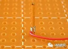
The circuit board is filled with densely packed conductive posts.
When you first hear the term “breadboard”, most people picture a large wooden board and freshly baked bread in their minds. In fact, this isn’t a completely wrong idea.

A long time ago, unlike today, electronic components occupied quite a large volume. Therefore, to connect electronic circuits, people would take large plates like breadboards from the kitchen, pull out nails, connect the electronic components and wires on the breadboard, and complete the circuit.
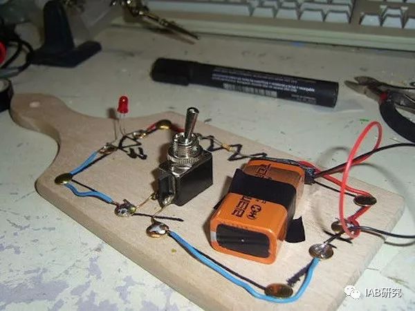
The electronic circuit on the breadboard (the real breadboard!) Since then, electronic components have become smaller and smaller, and people have started inventing new methods and tools for connecting electronic circuits. However, even at that time, the tools used for electronic practice did not have a unified name and continued to be called breadboards.
[Why Use a Breadboard?] Breadboards used for electronic circuit training (not the kind used for making sandwiches!) do not require soldering. Breadboards are ideal tools for prototyping electronic circuits. The best way to verify that a circuit works when completing an electronic project is to prototype and validate it.
For those unfamiliar with electronic circuits, breadboards are the best entry-level tools for circuit practice. This is the true advantage of breadboards, as they can be configured to relatively small sizes for both complex circuits and simple exercises.
[Internal Structure of a Breadboard]
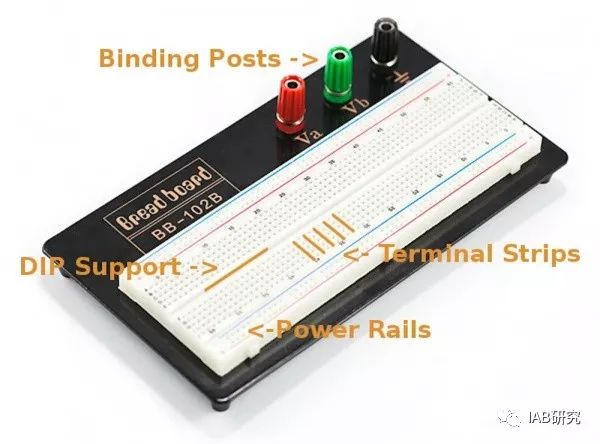
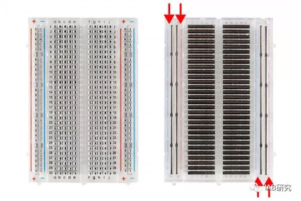
The best way to explain how a breadboard works is to open it up and look inside. If you open a small breadboard, you can see how it operates. Terminal strips: Remove the double-sided tape from the back of the breadboard, and you will see multiple rows of metal strips, as shown in the right image below.
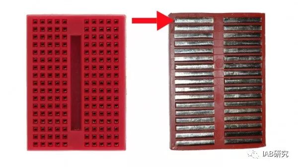
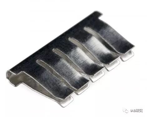
The top of the metal strips (the side with holes on the breadboard) is shaped like small clips, located beneath the plastic holes on the breadboard. The spacing of each metal strip is 0.1 inches (2.54 mm). The clip portion of the metal strip allows it to hold tightly onto the legs of electronic components inserted into the breadboard holes.
 As mentioned above, the parts connected in a row are electrically connected.This is because the metal strips are conductive, allowing current to flow regardless of where the parts are inserted.
As shown in the image above, a metal strip consists of five clips, and most breadboards are similar. This means that five rows can be accommodated in one row of a breadboard. However, a row of a breadboard consists of 10 holes. So why can only five components be inserted? If you look closely at the breadboard, you will find a gap in the middle that electrically insulates the metal strips on both sides. This insulation prevents current from flowing through by isolating heat across five holes.
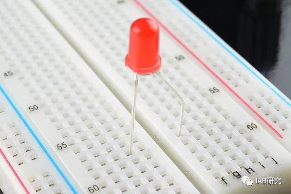 Each leg of an LED and the LED inserted into the breadboard are separated on either side of the pit. This prevents the two legs of the LED from short-circuiting.
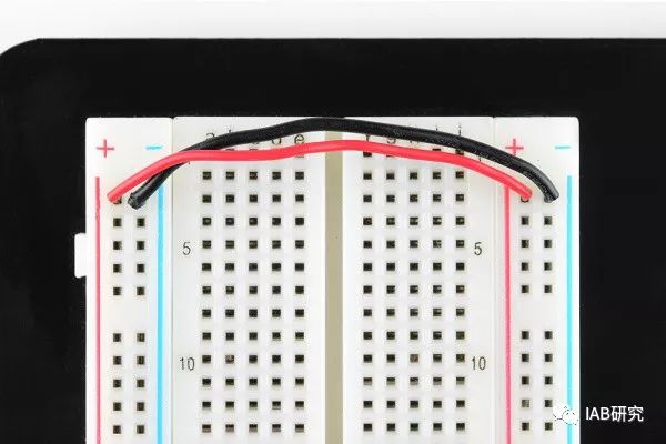
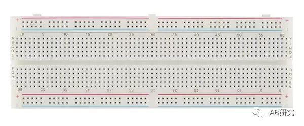
Let’s take another look at the power lines, which are a vertical hole on a typical breadboard, more commonly used than mini breadboards.
One thing to note is that the power lines on the left and right sides of the breadboard are not electrically connected. If you need to power through both power lines, connect the two sections with a wire, as shown in the image below.
DIP Support: I mentioned earlier that there is a pit in the center of the breadboard that insulates the two sides. This pit serves a very important purpose. Integrated circuits (commonly known as ICs) are typically assembled onto the breadboard. This type of IC is known as a dual in-line package (DIP). This DIP chip is made of a component pin that extends outward on both sides, allowing it to be inserted into the pit of the breadboard. As you know, each pin of the IC has a different function, so each pin must be electrically isolated. The insulation of the pit on the breadboard is very useful. Because if we insert a DIP chip into the pit, each pin can be easily electrically disconnected.
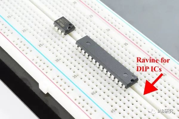
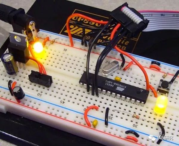
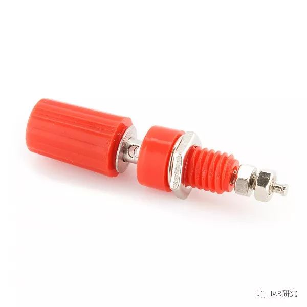
Two DIP chips, the LM358 (top) – a famous operational amplifier chip, and the ATmega328 microprocessor chip (bottom) The numbers written on the breadboard: Some very attentive people may notice that there are a few numbers written in five rows on the breadboard. In fact, these numbers are merely references for convenient circuit connections and are not very significant. In circuit practice, it is often difficult to visually identify circuit connections, even if the circuit is slightly complex. If you follow the circuit boards in electronic magazines or books, you can reduce the number of errors by connecting these numbers. However, this number does not necessarily mean that connections must be made at the same position along the circuit configuration. As long as the circuit works, it can be configured anywhere else on the breadboard. Terminal posts: Some breadboards have fixed terminal posts that can hang on wires. This post allows you to connect an external power supply to the breadboard.
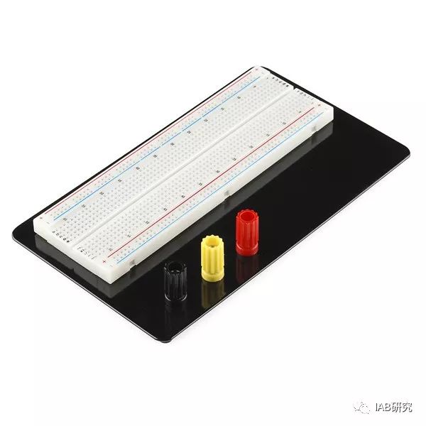
Some breadboards have double-sided tape on the back for sticking to surfaces. Note: Some breadboards have their power line centers separated left and right, as shown below. When you want to use two different external power supplies (for example, 3.3V and 5V) simultaneously, this test board is very convenient. However, if you are unsure whether the breadboard is divided into two parts, it is best to check with a multimeter before use.
[Powering the Breadboard] If you are using a development board like Arduino, you can simply get power from the power pins of the Arduino. Arduino has several power and ground pins that can easily power the breadboard.
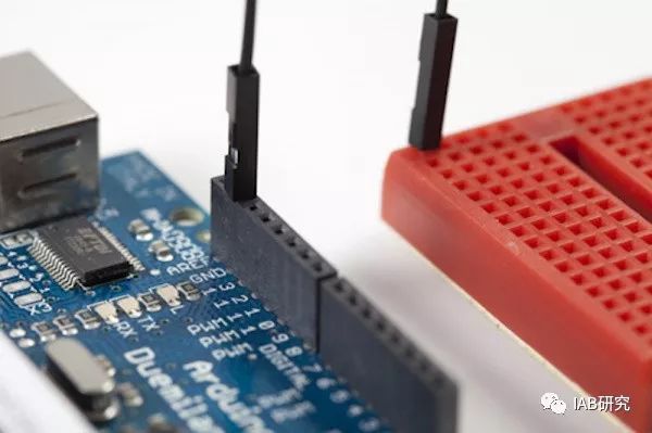 Connecting from Arduino’s GND pin to the terminal strip of the mini breadboard.Now, all pins connected to holes in the same row as the breadboard will connect to GND.
Arduino typically gets power from a computer’s USB port, an external battery pack, or an adapter.
The content of this article refers to the Sparkfun breadboard tutorial translation from the public account.

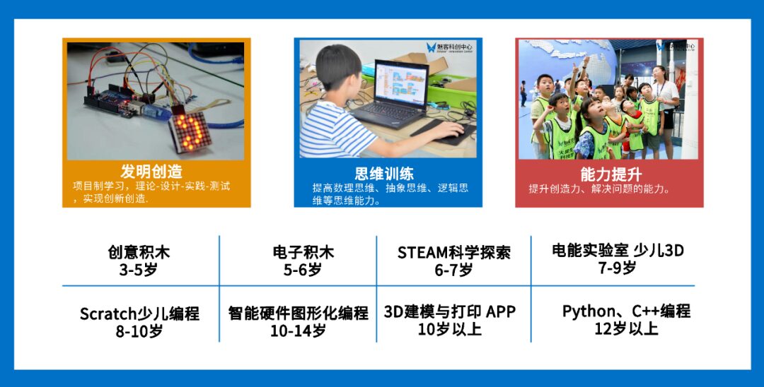
Meike Innovation Center courses are aimed at children and teenagers aged 3-18, based on the American STEAM interdisciplinary education concept, advocating hands-on innovation and creativity, covering fields such as robotics, science, programming, etc., allowing children to learn through creation.
Fostering a new generation of innovative youth, helping children become world-changers!

Tongzilun Campus 15928043843
Sichuan Science and Technology Museum Teaching Point 17612865976
Tianfu Yijie Campus 13438886121
Jinsha Campus 13980247344
Wenjiang Phoenix Neighborhood Campus 028-8268 8336
Wenjiang Xinguang Tiandi Campus 028-8269 3585
Wenjiang Huamu Li Campus 028-8262 8818
Shuangliu Xi’an Road Campus 028-8946 0008
Xipu Kaide Campus 028-8265 6080
Ya’an Yucheng Campus 15378682909
Ziyang Mangou Campus 028-2650 1183