Is industrial control software installation difficult? Here are 29 installation videos for programming software!
Today, I will mainly share a practical case involving a water level control project with PLC, inverter, and touch screen. Let’s take a look at the entire process, which you can save for future reference!
● Project Description
● EM235 Module
● Project Implementation
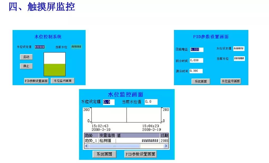
● Touch Screen Monitoring
I. Project Description
1. Project Control Requirements
The water tank supplies water to external users, and the water consumption is unstable, sometimes high and sometimes low. Water can be pumped into the tank, and we need to maintain a constant water level control within a range of 0~200mm (the maximum value can be determined based on the height of the water tank). For example, if the set water level in the tank is 100mm, regardless of the outflow, the inflow must be adjusted to maintain the water level at 100mm. If the outflow is low, the inflow should also be controlled to be low; if the outflow is high, the inflow should also be high.
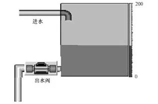
2. Control Strategy
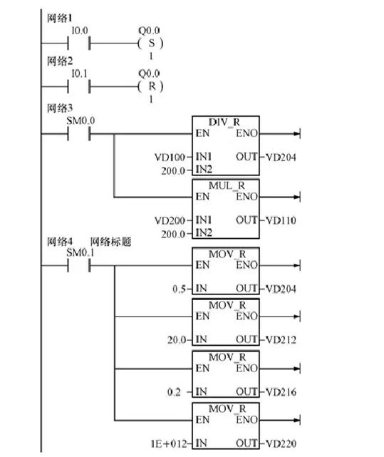
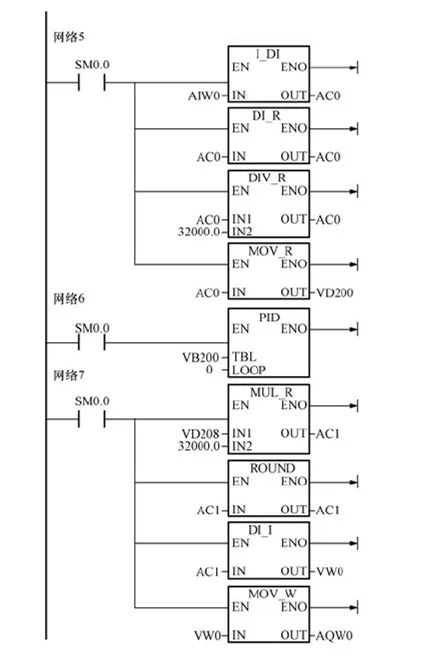
Since the liquid level height is proportional to the water pressure at the bottom of the tank, a pressure sensor can be used to detect the pressure at the bottom of the tank to determine the liquid level height. A PD algorithm is used for automatic adjustment of the water level. The level signal detected by the pressure sensor (4~20mA) is sent to the PLC, where the deviation between the set point and the detected value is calculated using PID. The result is then used to adjust the speed of the water pump motor, thereby regulating the inflow. The speed of the water pump motor can be adjusted using an inverter.
3. Component Selection
1) PLC and Module Selection. The PLC can use the S7-200 CPU224. To receive the analog signal from the pressure sensor and adjust the water pump motor speed, an EM235 analog input/output module is selected.
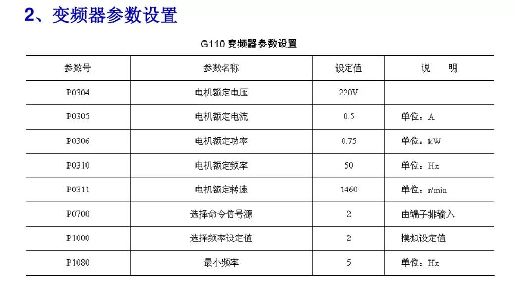
2) Inverter Selection. To adjust the inflow, the Siemens G110 inverter is selected.
3) Touch Screen Selection. The Siemens TP170B human-machine interface touch screen is selected.
4) The water tank equipment is shown in the figure below.
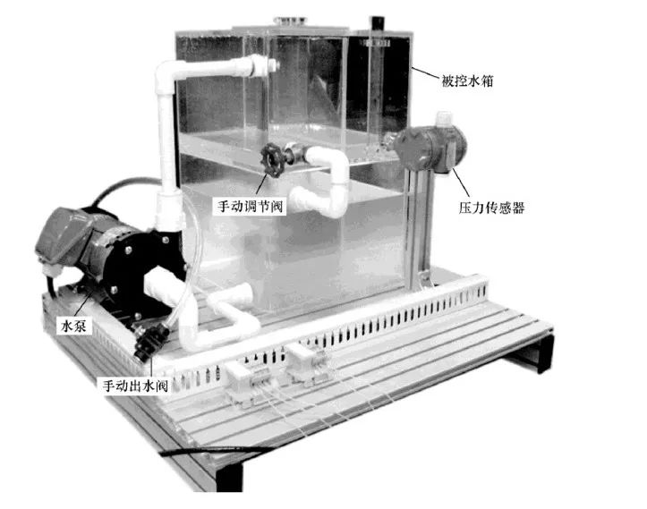
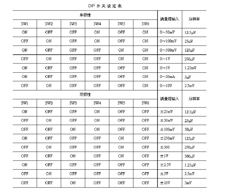
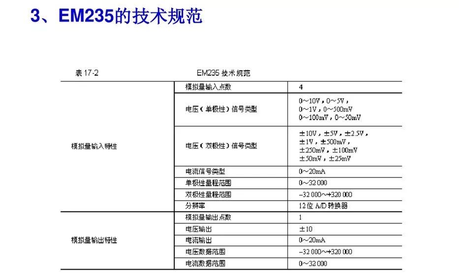
II. EM235 Module
Wiring and terminals of the EM235
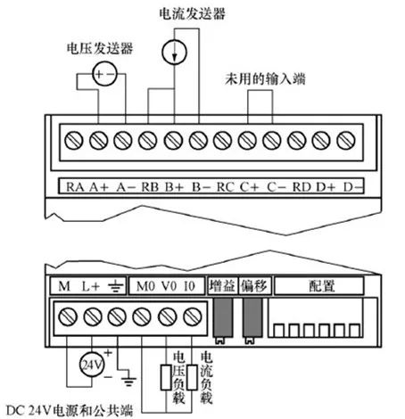
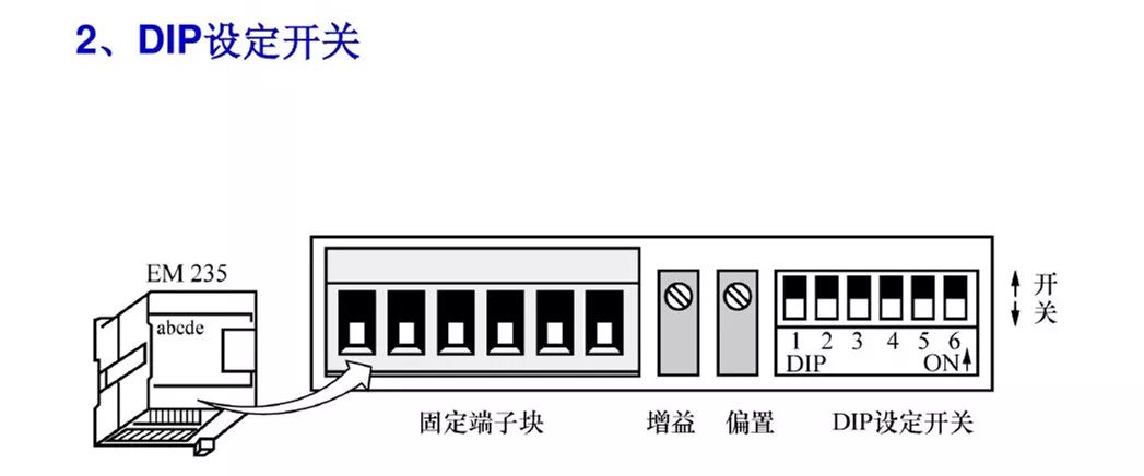
III. Project Implementation
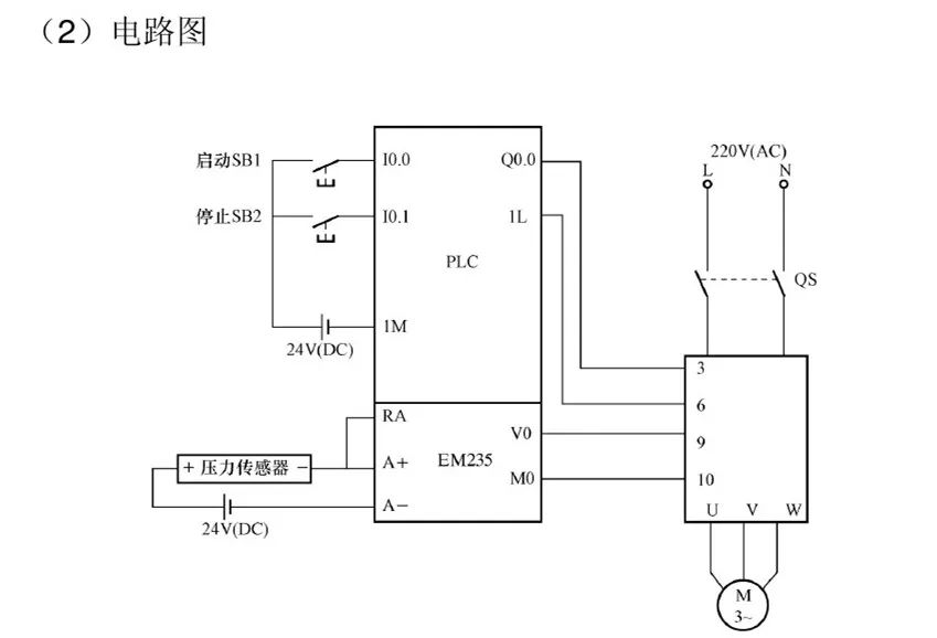
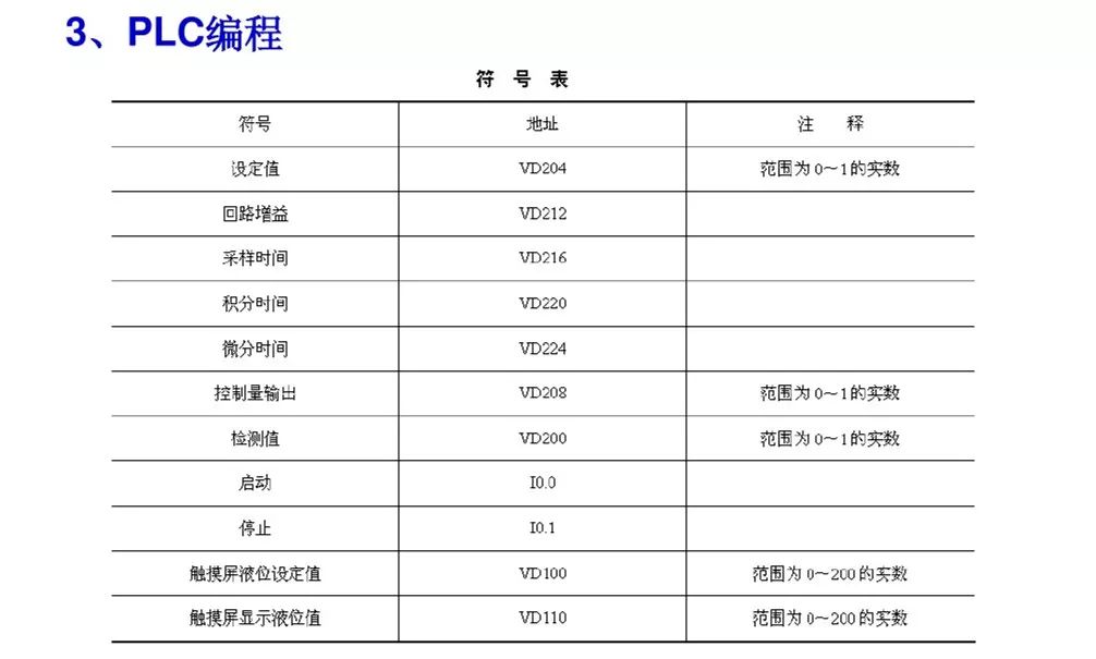
1. PLC IO Allocation and Circuit Diagram
PLC IO Allocation
Start Button, 10.0;
Stop Button, 10.1;
Q0.0, controls the operation of the water pump motor.
IV. Touch Screen Monitoring
Source: Internet, please contact for deletion if infringement occurs.