 Search on WeChat
 Technical Training
Introduction:
This article will detail the steps to connect the S7-200 SMART PLC with the MCGS touch screen via 485 communication.
1. Hardware Connection
01
MCGS Touch Screen 485 Port Pin Definition
Taking TPC7022Ew as an example, the pin definitions for the COM2 communication port are shown in Figure 1.
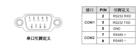
Figure 1
02
S7-200 SMART PLC 485 Port Pin Definition
The S7-200 SMART PLC can select the integrated RS485 communication port of the CPU or the standard CPU with additional support for the SB CM01 signal board. The pin allocation for the integrated RS485 communication port of the CPU is shown in Figure 2.
The standard CPU additionally supports the SB CM01 signal board, which can be configured as an RS485 communication port or RS232 communication port via the STEP 7-Micro/WIN SMART software. The pin allocation for the SB CM01 signal board is shown in Figure 3.
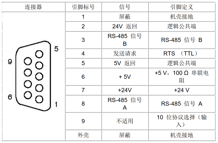
Figure 2
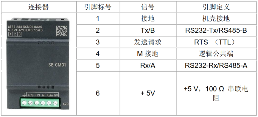
Figure 3
03
Connecting PLC and Touch Screen
3.1 Connecting the CPU Integrated RS485 Communication Port to the Touch Screen
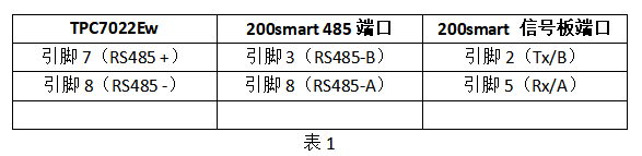
PLC port pin 3 connects to the touch screen COM2 port pin 7, and PLC port pin 8 connects to the touch screen COM2 port pin 8, as shown in Table 1.
3.2 Connecting the SB CM01 Signal Board to the Touch Screen
SB CM01 signal board Tx/B connects to the touch screen COM2 port pin 7, and SB CM01 signal board Rx/A connects to the touch screen COM2 port pin 8, as shown in Table 1.
2. MCGS Pro Software Settings
01
Create a New Project
Open the MCGS Pro software, create a new project in the file menu, and select the TPC7022Ew touch screen;
02
Create a New Connection Device
1) In the device window of the workspace, set up communication devices as shown in Figure 4; steps 3 and 4 require a double-click of the left mouse button, and a prompt will pop up in step 4, click confirm;
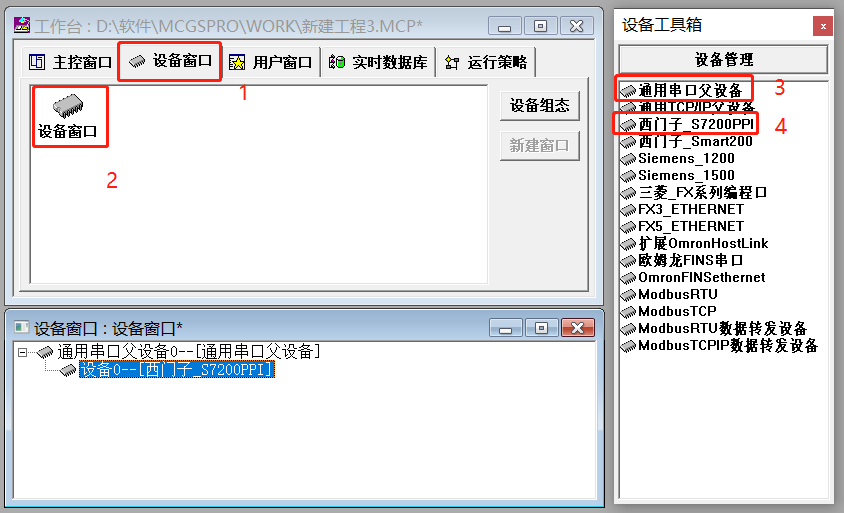
Figure 4
2) Set serial communication parameters based on the actual device’s communication parameters in step 2 of Figure 5;
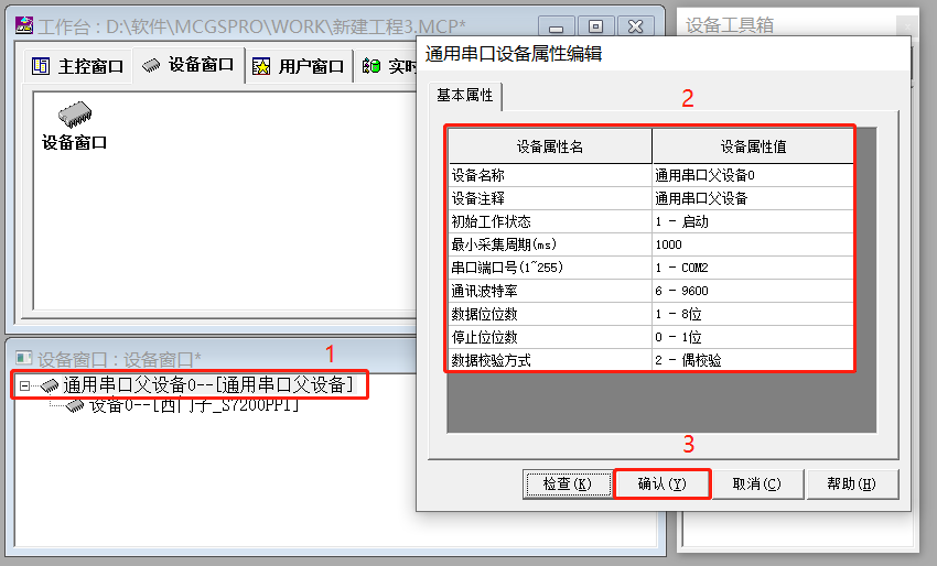
Figure 5
03
Create Connection Variables
1) Create a Bool variable;
Create variable V0.0 as shown in Figure 6.
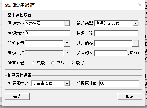
Figure 6
2) Create a Byte variable;
Create variable VB1 as shown in Figure 7.
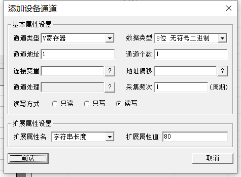
Figure 7
3) Create a Word variable;
Create variable VW2 as shown in Figure 8.
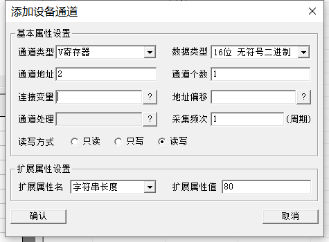
Figure 8
4) Create a DWord variable;
Create variable VD4 as shown in Figure 9.
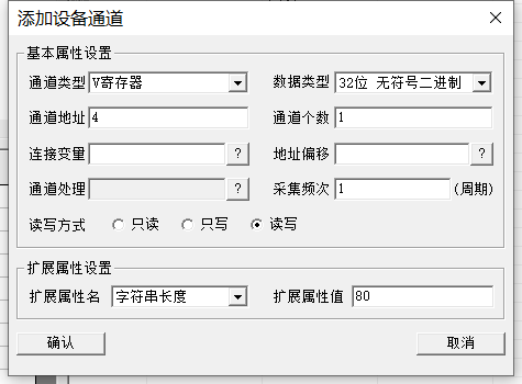
Figure 9
5) Create a Real variable;
Create variable VD8 as shown in Figure 10.
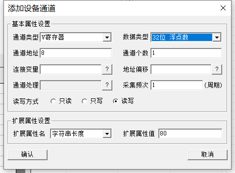
Figure 10
04
Connect Database
1) Quickly connect variables
As shown in Figures 11 and 12, follow the steps to quickly connect database variables.
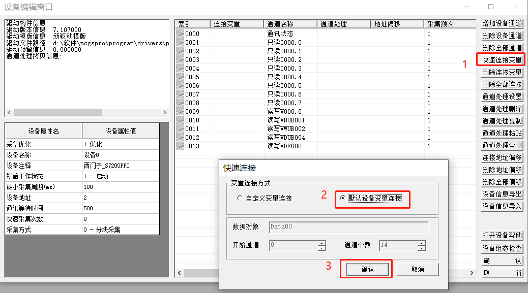
Figure 11
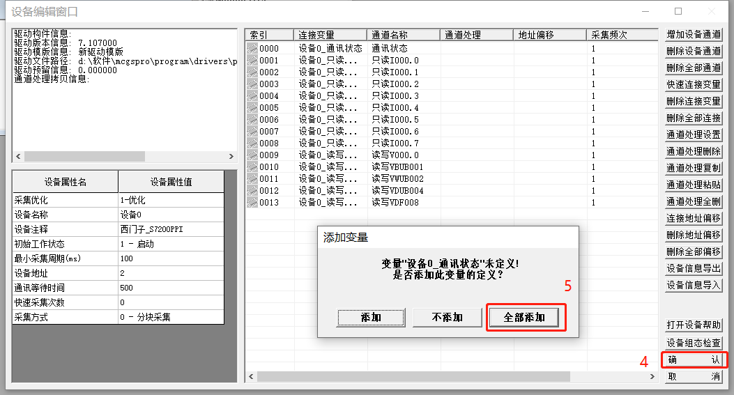
Figure 12
2) Modify Data Types
Select the variable in step 1 of Figure 13, then follow the steps to operate; in step 3, select the corresponding object type based on the variable, as shown in step 1 for the modified data type.
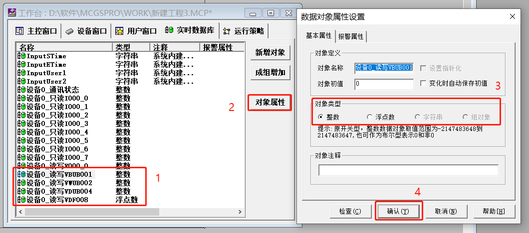
Figure 13
05
Configuration Programming
Configuration screen shown in Figure 14.
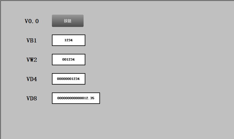
Figure 14
1) Button Configuration;
Configure the self-reset button V0.0, as shown in Figure 15.
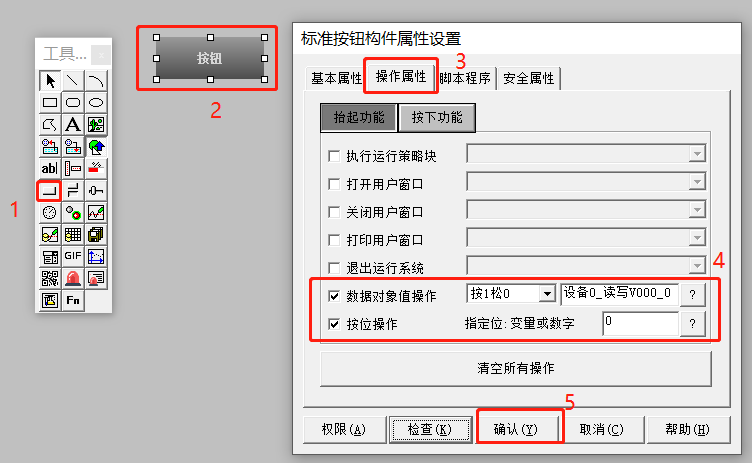
Figure 15
2) Input Box Configuration;
(1) Configure input box VB1, as shown in Figure 16.
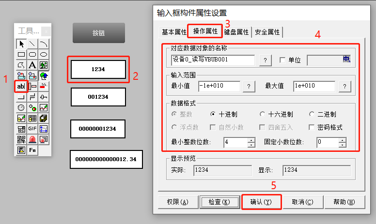
Figure 16
(2) Configure input box VW2, as shown in Figure 17.
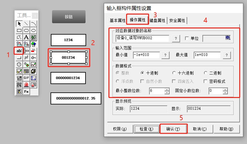
Figure 17
(3) Configure input box VD4, as shown in Figure 18.
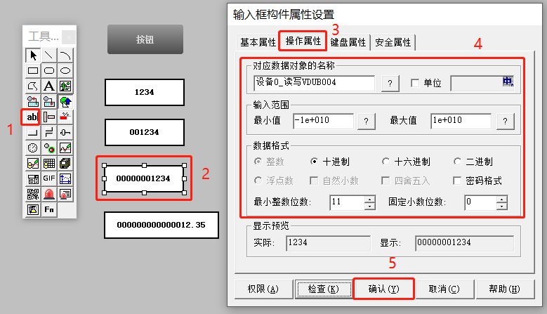
Figure 18
(4) Configure output display VD8, as shown in Figures 19 and 20.
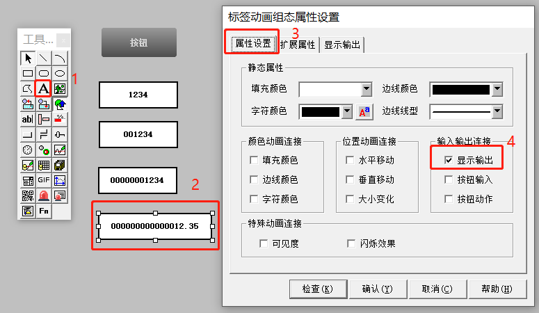
Figure 19
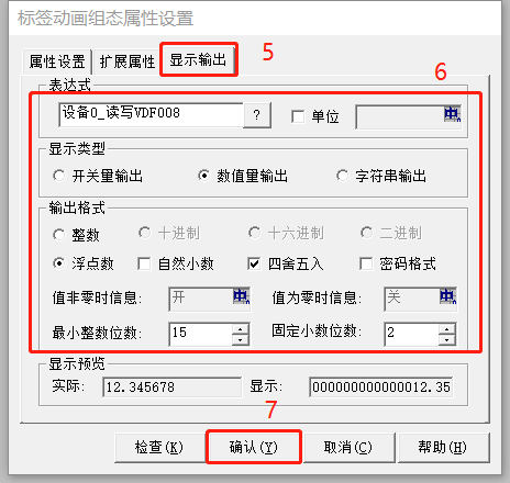
Figure 20
06
Configuration Program Download and Settings
1) Enter touch screen settings;
When the touch screen restarts, quickly click the logo in the touch screen display to enter system parameter settings, as shown in Figure 21.
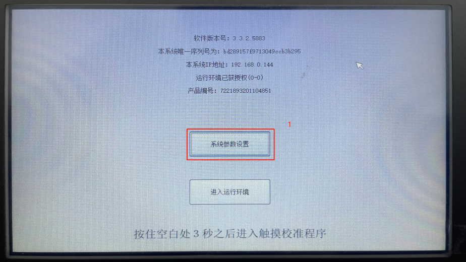
Figure 21
2) IP Address Settings;
After entering the touch screen system settings, modify the IP address of the touch screen to be in the same network segment as the computer, as shown in Figure 22.
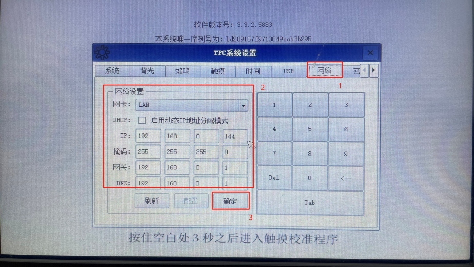
Figure 22
3) Configuration Program Download;
Download the configuration program as shown in Figure 23, fill in the touch screen IP address as the target machine name, and after successful download, as shown in step 5.
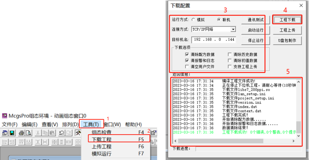
Figure 23
3. S7-200 SMART Software Settings
Open the STEP 7-MicroWIN SMART software, keep the system block parameters at default, no need for modification, as shown in Figure 24. No programming is required, then download the program to the PLC and switch to RUN mode.
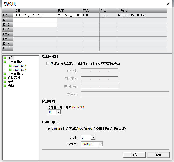
Figure 24
4. Connection Debugging
Switch the S7-200 SMART PLC to RUN mode, and connect the S7-200 SMART PLC to the MCGS touch screen using 485 wire. Modify data on the touch screen, as shown in Figure 25, and monitor data in the S7-200 SMART programming software status table, as shown in Figure 26. Successful communication indicates that the S7-200 SMART PLC and MCGS touch screen have successfully communicated.
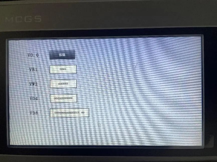
Figure 25
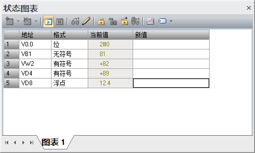
Figure 26
Conclusion:
The above content details all the steps for connecting the S7-200 SMART PLC with the MCGS touch screen via 485 communication. If there are any errors in the article, please contact us.
Pro Configuration Program


Scan to Receive
MCGS Pro Configuration Program
Note: The software requires MCGS PRO 3.2.2.5166 or above
Source: Technical Training Network Original, Author: Zou Zhirui; Reprinting without authorization is prohibited, and violators will be held accountable!
HISTORY/Previous Recommendations
Complete Question Bank for Electrical Worker Primary Examination 2021 (Including Answers)
Three Must-Have Tools for Electricians, One-Click Access via WeChat!
[Collection] The “Path” for Ten-Year Veteran Electricians, Secrets to Earning Over Ten Thousand a Month!
Top Five Electrical Drawing Software (CAD, Eplan, CADe_simu…), Which One Do You Pick?
Latest Electrical CAD Drawing Software, with Ultra-Detailed Installation Tutorial!
Latest Electrical Drawing Software EPLAN, with Ultra-Detailed Installation Tutorial!
Common Issues for Beginners Using S7-200 SMART Programming Software (Including Download Links)
Comprehensive Electrical Calculation EXCEL Spreadsheet, Automatically Generated! No Need to Ask for Electrical Calculations!
Bluetooth Headphones, Beginner Books for Electricians/PLC, Free Gifts Available! Come and Claim Your Electrical Gifts!
Basic Skills of PLC Programming: Ladder Diagrams and Control Circuits (Including 1164 Practical Cases of Mitsubishi PLC)
Still Can’t Understand Electrical Diagrams? Basic Electrical Diagram Recognition, Simulation Software Available, Quickly Get Started with Theory and Practice!
12 Free Electrical Video Courses, 10GB Software/Electronic Book Materials, 30 Days of Free Live Electrical Courses!
Don’t Forget to Like + View!

 Click “Read Original” to Learn PLC/Electrician Courses for Free