
☞ This is the 13639th article published by Metal Processing (mw1950pub)

Editor’s Note
PLC, inverters, and human-machine interfaces are important devices in modern industrial automation control. The application of these devices makes the production and manufacturing processes in factories more automated, efficient, precise, and controllable, greatly promoting the automation process of China’s manufacturing industry and making a significant contribution to the modernization of our country.
A touch screen is a digital input/output device with touch display functionality, also known as a human-machine interface (HMI). When the touch screen is connected to a PLC, it can not only operate the PLC but also monitor the working status of some soft components inside the PLC in real-time on the touch screen. To use the touch screen to operate and monitor the PLC, it is necessary to create (also known as configuration) the corresponding operation and monitoring screen projects for the touch screen using specialized configuration software on a computer, and then download the screen projects to the touch screen.
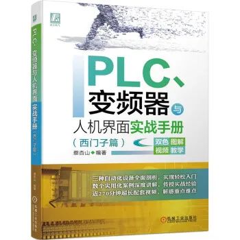
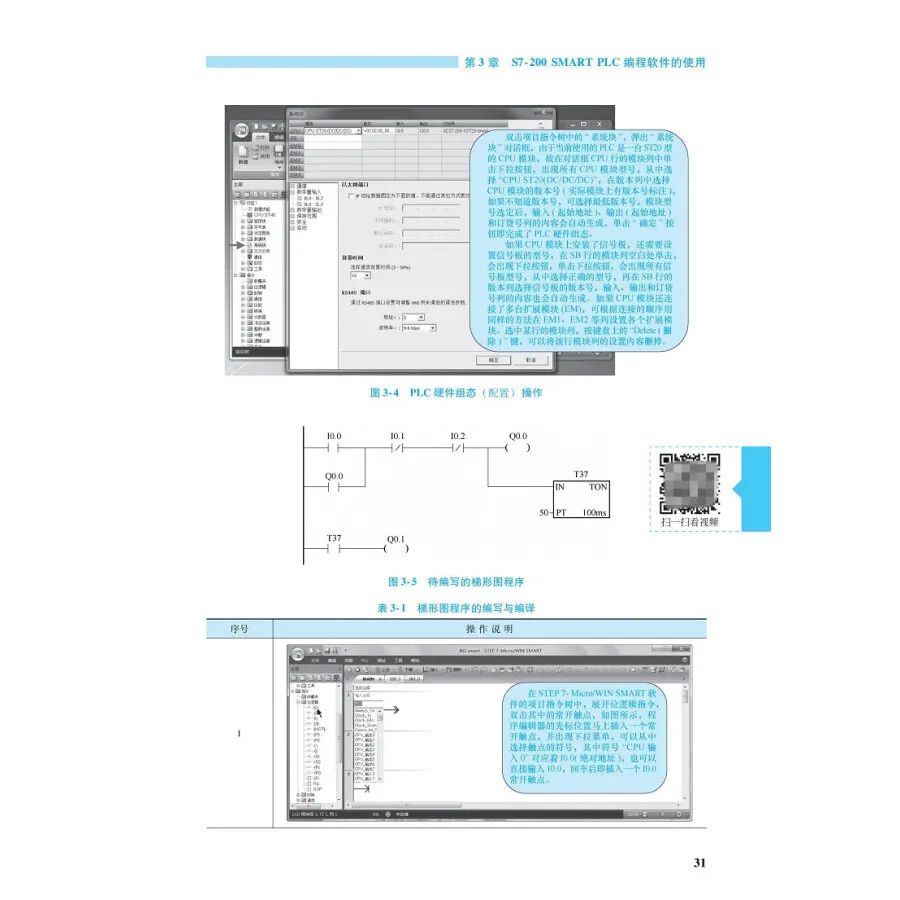
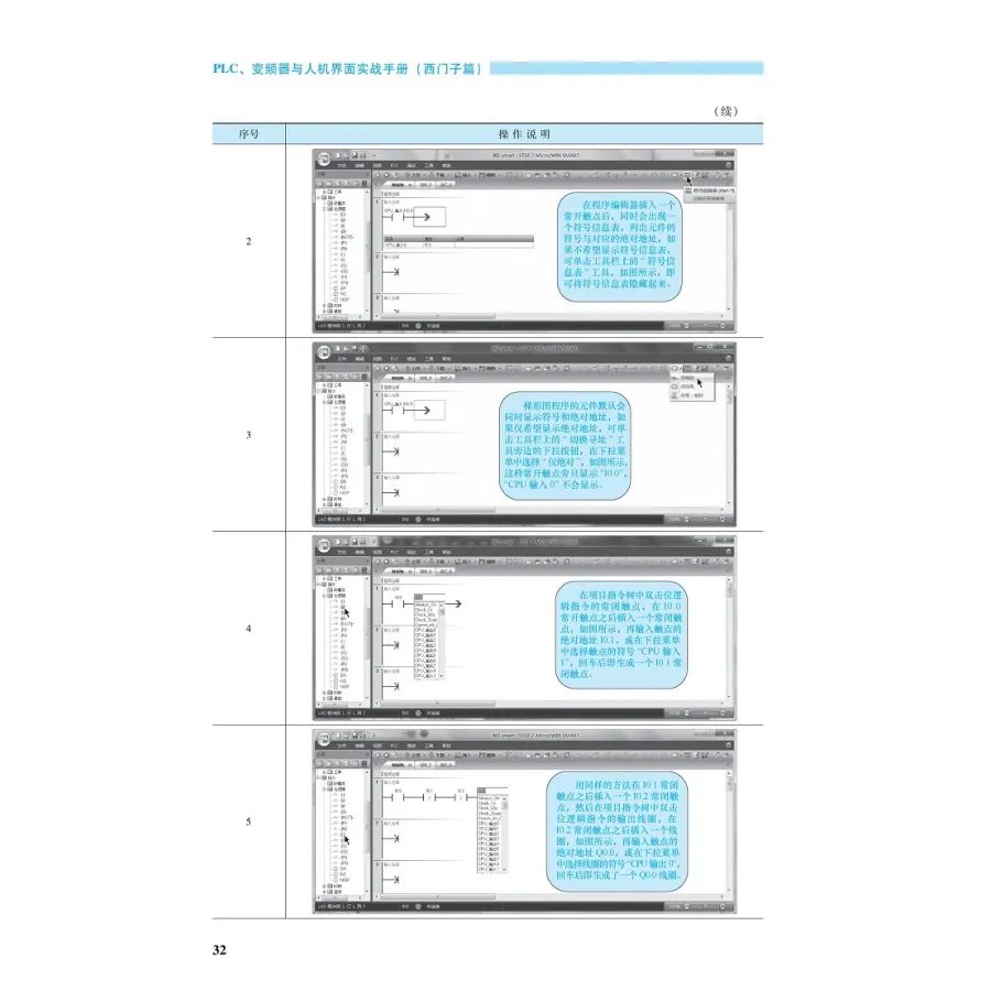
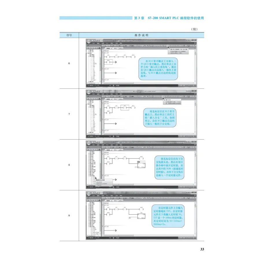
Today, I would like to introduce a book titled Practical Handbook on PLC, Inverters, and HMI (Siemens Edition), which introduces Siemens PLC, inverter, and human-machine interface configuration technology. The main content includes the basics of PLC and practical entry into Siemens PLC, introduction to Siemens S7-200 SMART PLC, usage of S7-200 SMART PLC programming software, usage and examples of basic instructions, usage and examples of sequential control instructions, usage and examples of functional instructions, PLC communication, usage of Siemens inverters, inverter application circuits, comprehensive application of PLC and inverter, introduction to Siemens touch screens, quick entry into Siemens WinCC configuration software, usage of common objects in WinCC software, and practical operation of PLC controlled by Siemens touch screen.
Click the image to purchase
Book Features
Preface
Chapter 1 Basics of PLC and Practical Entry into Siemens PLC
1.1 What is PLC
1.1.2 Comparison of PLC Control and Relay Control
1.2 Types and Characteristics of PLC
1.2.1 Types of PLC
1.2.2 Characteristics of PLC
1.3 Composition and Working Principle of PLC
1.3.1 Composition Block Diagram of PLC
1.3.2 CPU and Memory
1.3.3 Input Interface Circuit
1.3.4 Output Interface Circuit
1.3.5 Communication Interface, Expansion Interface, and Power Supply
1.3.6 Working Mode of PLC
1.3.7 Example of the Working Process of PLC Control Circuit
1.4 Programming Languages of PLC
1.4.1 Ladder Diagram
1.4.2 Function Block Diagram
1.4.3 Instruction Statement Table
1.5 Development Example of Siemens PLC Control of Dual Lights
1.5.1 General Process of PLC Application System Development
1.5.2 Control Requirements of the System
1.5.3 Select PLC Model and Determine Input/Output Devices and I/O Terminals
1.5.4 Draw the Circuit Diagram of PLC Control of Dual Lights
1.5.5 Write PLC Program Using Programming Software
1.5.6 DC24V Power Adapter and Power Line
1.5.7 Connect Computer and PLC with Programming Cable
1.5.8 Download Program to PLC
1.5.9 Simulated Debugging
1.5.10 Actual Wiring
1.5.11 Actual Operation Testing
Chapter 2 Introduction to Siemens S7-200 SMART PLC
2.1 Introduction to PLC Hardware
2.1.1 Two Types of CPU Modules
2.1.2 Explanation of Components on CPU Module Panel
2.1.3 Wiring of CPU Module
2.1.4 Installation and Use of Signal Boards and Address Allocation
2.1.5 Common Modules and Order Numbers of S7-200 SMART PLC
2.2 Soft Components of PLC
2.2.1 Input Relays and Output Relays
2.2.2 Auxiliary Relays, Special Auxiliary Relays, and Status Relays
2.2.3 Timers, Counters, and High-Speed Counters
2.2.4 Accumulators, Variable Memory, and Local Variable Memory
2.2.5 Analog Input Registers and Analog Output Registers
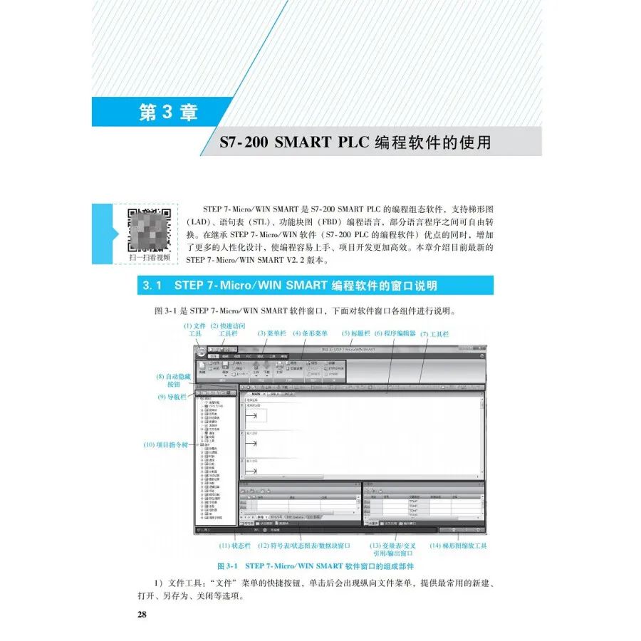
Chapter 3 Using S7-200 SMART PLC Programming Software
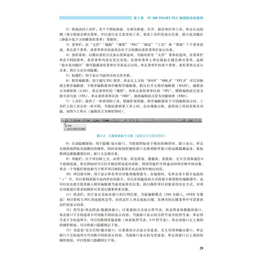
3.1 Explanation of STEP7-Micro/WIN SMART Programming Software Window
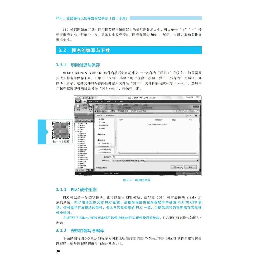
3.2 Writing and Downloading Programs
3.2.1 Creating and Saving Projects
3.2.2 PLC Hardware Configuration
3.2.3 Writing and Compiling Programs
3.2.4 Connection and Communication Settings Between PLC and Computer
3.3 Editing and Commenting Programs
3.3.1 Editing Programs
3.3.2 Commenting Programs
3.4 Monitoring and Debugging Programs
3.4.1 Monitoring and Debugging Programs with Ladder Diagrams
3.4.2 Monitoring and Debugging Programs with State Chart Tables and Trend Graphs
3.4.3 Monitoring and Debugging Programs with State Chart Trends
3.5 Object Settings, Hardware Configuration, and Data Copying
3.5.1 Settings for Common Objects
3.5.2 Hardware Configuration
3.5.3 Backing Up, Copying Programs, and Refreshing Firmware with Storage Cards
Chapter 4 Usage and Examples of Basic Instructions
4.1 Bit Logic Instructions
4.1.1 Contact Instructions
4.1.2 Coil Instructions
4.1.3 Immediate Instructions
4.1.4 RS Trigger Instructions
4.1.5 No Operation Instructions
4.2 Timers
4.2.1 On Delay Timer
4.2.2 Off Delay Timer
4.2.3 Memory On Delay Timer
4.3 Counters
4.3.1 Up Counter
4.3.2 Down Counter
4.3.3 Up/Down Counter
4.4 Common Basic Control Circuits and Ladder Diagrams
4.4.1 Start, Self-Locking, and Stop Control Circuits and Ladder Diagrams
4.4.2 Forward and Reverse Interlocking Control Circuits and Ladder Diagrams
4.4.3 Multi-location Control Circuits and Ladder Diagrams
4.4.4 Timing Control Circuits and Ladder Diagrams
4.4.5 Long Timing Control Circuits and Ladder Diagrams
4.4.6 Multiple Output Control Circuits and Ladder Diagrams
4.4.7 Overload Alarm Control Circuits and Ladder Diagrams
4.4.8 Flashing Control Circuits and Ladder Diagrams
4.5 Example of Siemens PLC Control of Fountain
4.5.1 System Control Requirements
4.5.2 I/O Terminals and Input/Output Devices
4.5.3 PLC Control Circuit
4.5.4 PLC Control Program and Detailed Explanation
4.6 Example of Siemens PLC Control of Traffic Lights
4.6.1 System Control Requirements
4.6.2 I/O Terminals and Input/Output Devices
4.6.3 PLC Control Circuit
4.6.4 PLC Control Program and Detailed Explanation
4.7 Example of Siemens PLC Control of Multi-level Conveyor Belt
4.7.1 System Control Requirements
4.7.2 I/O Terminals and Input/Output Devices
4.7.3 PLC Control Circuit
4.7.4 PLC Control Program and Detailed Explanation
4.8 Example of Siemens PLC Control of Automatic Garage Door
4.8.1 System Control Requirements
4.8.2 I/O Terminals and Input/Output Devices
4.8.3 PLC Control Circuit
4.8.4 PLC Control Program and Detailed Explanation
Chapter 5 Usage and Examples of Sequential Control Instructions
5.1 Sequential Control and State Transition Diagrams
5.2 Sequential Control Instructions
5.2.1 Instruction Names and Functions
5.2.2 Examples of Instruction Usage
5.2.3 Precautions for Instruction Usage
5.3 Several Methods of Sequential Control
5.3.1 Selective Branching Method
5.3.2 Parallel Branching Method
5.4 Example of Siemens PLC Control of Liquid Mixing Device
5.4.1 System Control Requirements
5.4.2 I/O Terminals and Input/Output Devices
5.4.3 PLC Control Circuit
5.4.4 PLC Control Program and Detailed Explanation
5.5 Example of Siemens PLC Control of Simple Robotic Arm
5.5.1 System Control Requirements
5.5.2 I/O Terminals and Input/Output Devices
5.5.3 PLC Control Circuit
5.5.4 PLC Control Program and Detailed Explanation
5.6 Example of Siemens PLC Control of Sorting Machine for Small and Large Balls
5.6.1 System Control Requirements
5.6.2 I/O Terminals and Input/Output Devices
5.6.3 PLC Control Circuit
5.6.4 PLC Control Program and Detailed Explanation
Chapter 6 Usage and Examples of Functional Instructions
6.1 Data Types
6.1.1 Word Length
6.1.2 Types and Ranges of Data
6.1.3 Programming Format for Constants
6.2 Transfer Instructions
6.2.1 Single Data Transfer Instruction
6.2.2 Byte Immediate Transfer Instruction
6.2.3 Data Block Transfer Instruction
6.2.4 Byte Swap Instruction
6.3 Comparison Instructions
6.3.1 Byte Contact Comparison Instruction
6.3.2 Integer Contact Comparison Instruction
6.3.3 Double Word Integer Contact Comparison Instruction
6.3.4 Real Number Contact Comparison Instruction
6.3.5 Examples of Comparison Instruction Applications
6.4 Mathematical Operation Instructions
6.4.1 Addition, Subtraction, Multiplication, and Division Instruction
6.4.2 Floating Point Function Operation Instruction
6.5 Logic Operation Instructions
6.5.1 NOT Instruction
6.5.2 AND Instruction
6.5.3 OR Instruction
6.5.4 XOR Instruction
6.6 Shift and Rotate Instructions
6.6.1 Left and Right Shift Instructions
6.6.2 Circular Left and Right Shift Instructions
6.7 Conversion Instructions
6.7.1 Standard Conversion Instructions
6.7.2 ASCII Code Conversion Instructions
6.8 Table Instructions
6.8.1 Fill Table Instructions
6.8.2 Lookup Table Instructions
6.9 Clock Instructions
6.9.1 Explanation of Clock Instructions
6.9.2 Examples of Clock Instruction Usage
6.10 Program Control Instructions
6.10.1 Jump and Label Instructions
6.10.2 Loop Instructions
6.10.3 End, Stop, and Monitor Timer Reset Instructions
6.11 Subprograms and Subprogram Instructions
6.11.1 Subprograms
6.11.2 Subprogram Instructions
6.12 Interrupt Events and Interrupt Instructions
6.12.1 Interrupt Events and Interrupt Priorities
6.12.2 Interrupt Instructions
Chapter 7 PLC Communication
7.1 Basic Knowledge of Communication
7.1.1 Communication Methods
7.1.2 Communication Transmission Media
7.2 PLC Ethernet Communication
7.2.1 Device Types for Ethernet Connection of S7-200 SMART PLC CPU Module
7.2.2 Setting IP Addresses
7.2.3 Ethernet Communication Instructions
7.2.4 Example of PLC Ethernet Communication
7.3 PLC RS-485/RS-232 Communication
7.3.1 RS-232C, RS-422A, and RS-485 Interface Circuit Structure
7.3.2 RS-485/RS-232 Pin Function Definitions
7.3.3 Get Port Address Instruction and Set Port Address Instruction
7.3.4 Send and Receive Instructions
Chapter 8 Usage of Siemens Inverters
8.1 Basic Structure and Principles of Inverters
8.1.1 Two Speed Control Methods for Induction Motors
8.1.2 Structure and Principles of Two Types of Inverters
8.2 Structure and Wiring of Siemens MM440 Inverter
8.2.1 Appearance and Meaning of Model Number
8.2.2 Internal Structure and External Wiring Diagram
8.2.3 Wiring of External Terminals of Main Circuit
8.2.4 Typical Actual Wiring of Control Circuit External Terminals
8.2.5 Wiring and Parameter Settings for Digital Input Terminals
8.2.6 Wiring and Parameter Settings for Analog Input Terminals
8.2.7 Wiring and Parameter Settings for Digital Output Terminals
8.2.8 Wiring and Parameter Settings for Analog Output Terminals
8.3 Stopping, Braking, and Restarting Methods of Inverters
8.3.1 Motor Nameplate Data and Corresponding Parameters of Inverter
8.3.2 Stopping Methods of Inverter
8.3.3 Braking Methods of Inverter
8.3.4 Restarting Methods of Inverter
8.4 Operating and Debugging Inverters with Panels and External Terminals
8.4.1 Operating and Debugging Inverters with SDP and External Terminals
8.4.2 Operating and Debugging Inverters with BOP
8.4.3 Operating and Debugging Inverters with AOP
8.5 Parameter Debugging and Routine Operation of MM440 Inverter
8.5.1 Resetting All Parameters of Inverter
8.5.2 Steps and Instructions for Quick Parameter Debugging of Inverter
8.5.3 Routine Operation of Inverter
Chapter 9 Inverter Application Circuits
9.1 Inverter Circuit for Controlling Forward and Reverse Rotation and Speed Adjustment with Panel Keyboard
9.1.1 Control Requirements
9.1.2 Circuit and Operation Instructions
9.1.3 Parameter Settings
9.2 Inverter Circuit for Controlling Forward and Reverse Rotation and Speed Adjustment with Panel Potentiometer
9.2.1 Control Requirements
9.2.2 Circuit and Operation Instructions
9.2.3 Parameter Settings
9.3 Multi-speed Control of Inverter and Application Circuits
9.3.1 Three Methods of Multi-speed Control of Inverter
9.3.2 Application Circuits for Multi-speed Control of Inverter
9.4 PID Control Circuit of Inverter
9.4.1 Principles of PID Control
9.4.2 Parameters Related to PID
9.4.3 Inverter Circuit and Parameter Settings for PID Control of Constant Pressure Water Supply
Chapter 10 Comprehensive Application of PLC and Inverter
10.1 PLC Control of Inverter to Drive Motor with Delayed Forward and Reverse Rotation Circuit
10.1.1 Control Requirements
10.1.2 Distribution of PLC Input and Output Terminals
10.1.3 Circuit Wiring
10.1.4 Parameter Settings of Inverter
10.1.5 PLC Control Program and Explanation
10.2 PLC Control of Inverter to Achieve Multi-speed Operation Circuit
10.2.1 Control Requirements
10.2.2 Distribution of PLC Input and Output Terminals
10.2.3 Circuit Wiring
10.2.4 Parameter Settings of Inverter
10.2.5 PLC Control Program and Explanation
10.3 Application Example of PLC Controlling Inverter via USS Protocol
10.3.1 Hardware Connection for S7-200 PLC and MM440 Inverter Serial Communication
10.3.2 USS Protocol
10.3.3 Installing USS Communication Library in S7-200 PLC Programming Software
10.3.4 USS Communication Instructions
10.3.5 Application Example of S7-200 PLC Controlling MM440 Inverter via USS Protocol
Chapter 11 Introduction to Siemens Touch Screens
11.1 Basic Knowledge of Touch Screens
11.1.1 Basic Components
11.1.2 Working Principles
11.2 Introduction to Siemens Exciting Series Touch Screens
11.2.1 Features of SMARTLINE Touch Screens
11.2.2 Common Models and Shapes
11.2.3 Explanation of Main Components of Touch Screens
11.2.4 Technical Specifications
11.3 Connection of Touch Screens with Other Devices
11.3.1 Power Wiring of Touch Screens
11.3.2 Ethernet Connection of Touch Screen with Configuration Computer
11.3.3 Connection of Touch Screen with Siemens PLC
11.3.4 Connection of Touch Screen with Mitsubishi, Schneider, and Omron PLCs
Chapter 12 Quick Entry into Siemens WinCC Configuration Software
12.1 Installation of WinCC flexible SMART V3 Software
12.1.1 System Requirements
12.1.2 Downloading and Installing Software
12.2 Configuring a Simple Project with WinCC Software
12.2.1 Creating and Saving Projects
12.2.2 Configuring Variables
12.2.3 Configuring Screens
12.2.4 Simulated Running of the Project
Chapter 13 Usage of Common Objects in WinCC Software
13.1 Example of Using IO Domains
13.1.1 Configuring Tasks
13.1.2 Configuring Processes
13.1.3 Running Tests
13.2 Example of Using Buttons
13.2.1 Configuring Tasks
13.2.2 Configuring Processes
13.2.3 Running Tests
13.3 Example of Using Variable Control Object Animations
13.3.1 Configuring Tasks
13.3.2 Configuring Processes
13.3.3 Running Tests
13.3.4 Simulation Debugging
13.4 Example of Using Pointer Variables
13.4.1 Configuring Tasks
13.4.2 Configuring Processes
13.4.3 Running Tests
13.5 Example of Using Switches and Drawing Tools
13.5.1 Configuring Tasks
13.5.2 Configuring Processes
13.5.3 Running Tests
13.6 Example of Using Alarm Functions
13.6.1 Basic Knowledge of Alarms
13.6.2 Configuring Tasks
13.6.3 Configuring Processes
13.6.4 Running Tests
13.7 Example of Using Bar Charts and Trend Charts
13.7.1 Configuring Tasks
13.7.2 Configuring Processes
13.7.3 Running Tests
13.8 Example of Using Screen Switching
13.8.1 Creating Screens
13.8.2 Setting Screen Switching with Drag-and-Drop Button Generation
13.8.3 Implementing Specified Screen Switching with Buttons
13.8.4 Implementing Any Numbered Screen Switching with Buttons
Chapter 14 Practical Operation of PLC Controlled by Siemens Touch Screen
14.1 Clarifying Requirements, Planning Variables, and Circuits
14.1.1 Control Requirements
14.1.2 Selecting PLC and Touch Screen Models and Allocating Variables
14.1.3 Device Connection and Circuit
14.2 Writing and Downloading PLC Programs
14.2.1 Writing PLC Programs
14.2.2 Connection and Settings Between PLC and Computer
14.2.3 Downloading and Uploading PLC Programs
14.3 Configuring and Downloading Touch Screen Screen Projects
14.3.1 Creating Touch Screen Screen Project Files
14.3.2 Configuring Connection Between Touch Screen and PLC
14.3.3 Configuring Variables
14.3.4 Configuring Indicator Lights
14.3.5 Configuring Buttons
14.3.6 Configuring Status Value Monitors
14.3.7 Configuring Instruction Texts
14.3.8 Downloading Projects to Touch Screen
14.3.9 Common Reasons and Solutions for Project Download Failures
14.3.10 Updating Touch Screen Version with ProSave Software
14.4 Operation and Monitoring Testing of Siemens Touch Screen Connected to PLC
14.4.1 Hardware Connection and Communication Settings of Touch Screen Connected to PLC with Ethernet Cable
14.4.2 Hardware Connection and Communication Settings of Touch Screen Connected to PLC with Serial Cable
14.4.3 Actual Operation Testing of Siemens Touch Screen Connected to PLC
Source: Jinfen Mall


Welder + Welding Robot Operation Skills Fully Covered
Essential for Hardware Data Reference
Explaining CNC Machine Fault Diagnosis and Maintenance with Examples