Search on WeChat
 Industrial Control Learning Community
MCGS, as the name suggests, refers to Kunlun Tongtai Touch Screen. The MCGS configuration software consists of three versions: embedded version, general version, and network version. The PRO version is currently mainstream, and here we will explain the online simulation Ethernet communication between MCGS PRO version and S7-200 SMART.
01Software Configuration
Step 1: (Open the Mcgs Pro configuration software shortcut on the desktop)


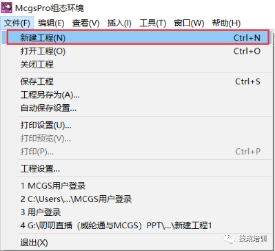
Step 2: (File menu in the top left corner of the software – New Project)
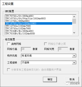
Step 3: (Project Settings – HMI Configuration)
Select the actual touch screen model or the model you need to simulate
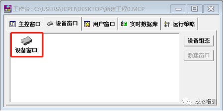
Step 4: (Open the Workbench – Device Window – Double-click the Device Window))
Step 5: (In the Device Window, click on a blank area and right-click to select Device Toolbox)
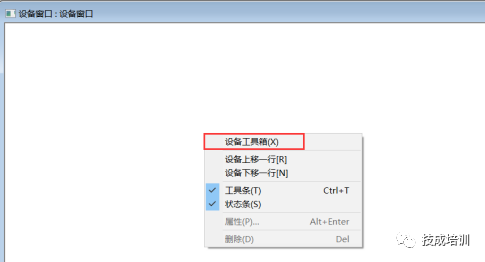
Step 6: (Click Device Management to open Device Configuration Settings)
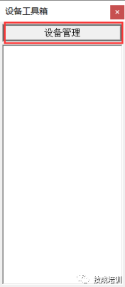
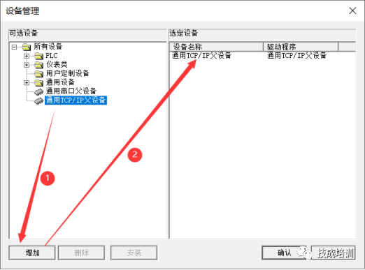
Step 7: (Select General TCP/IP Parent Device, click Add, the selected device on the right will be automatically added.)
Reminder: Why choose General TCP/IP Parent Device here? Because you need to add a master device to add child devices, where child devices refer to communication PLCs, instruments, inverters, etc.!
Step 8: (Select Siemens Smart200, click Add, the selected device on the right will be automatically added.)
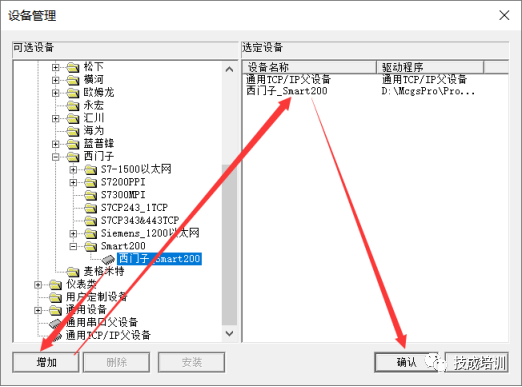
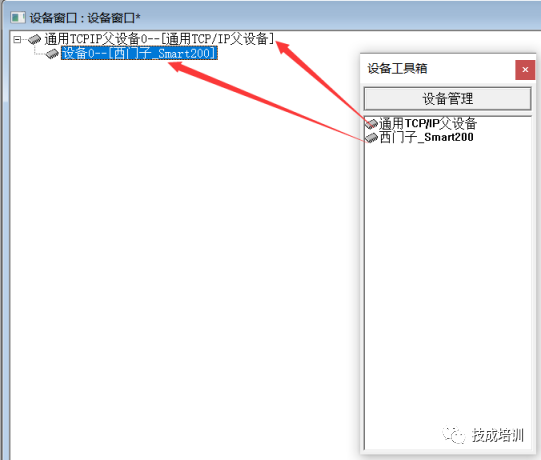
Step 9: (Device Toolbox – Device Management – Click General TCP/IP Parent Device – Siemens_Smart200 into the Device Window)
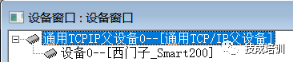
Step 10: (Double-click to open General TCPIP Parent Device 0–[General TCP/IP Parent Device] to enter Communication Configuration)
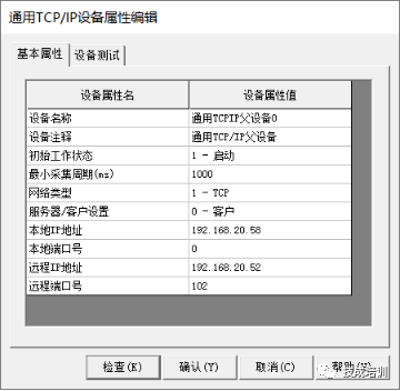
Step 11: (Fill in the IP address in the device property values)
Local IP Address:192.168.20.58 (Fill in the touch screen IP address for the device, fill in the computer’s local connection IP address for simulation)
Remote IP Address:192.168.20.52 (Fill in the PLC communication IP address)
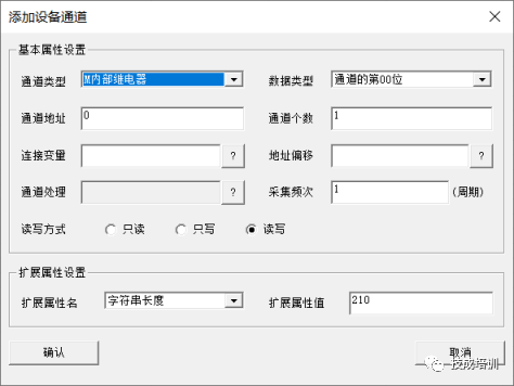
Step 12: (Add device channel, add PLC variable address)
Channel Type:M Internal Relay
Data Type:Bit 0 (indicates the number of decimal places after the PLC address variable, for example, if my address is M0.0, then the data type should fill in the 00th bit of the channel)
Channel Address:0 (indicates the starting byte address before the decimal point, for example, if my address is M0.0, then it should fill in 0 in the channel).
Channel Count:Represents the number of consecutive bits.
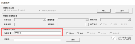
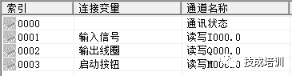
Step 13: (Double-click to open the connection variable – select from the data center – input the address corresponding symbol name for the connection variable)
All variables in MCGS are addressed by symbols, so you must create the corresponding symbols for the addresses; otherwise, they cannot be associated.
02Programming
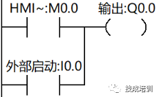
Step 1: (Write the jog program in STEP 7-MicroWIN SMART programming software)
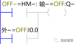
Step 2: (Download to PLC and monitor)
03Screen Design
Step 1: (Workbench – Click User Window – Click New Window – Double-click to open Window 0)
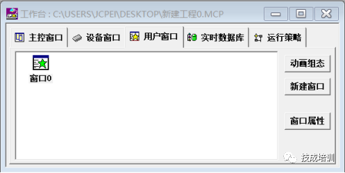
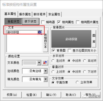
Step 2: (Toolbox – Standard Button – Basic Properties Input Start Button)
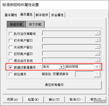
Operation properties – check data object value operation – select negate – click the question mark to associate with the corresponding symbol.
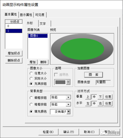
Step 3: (Toolbox – Animation Display – Basic Properties – Select Images Corresponding to States 0 and 1)
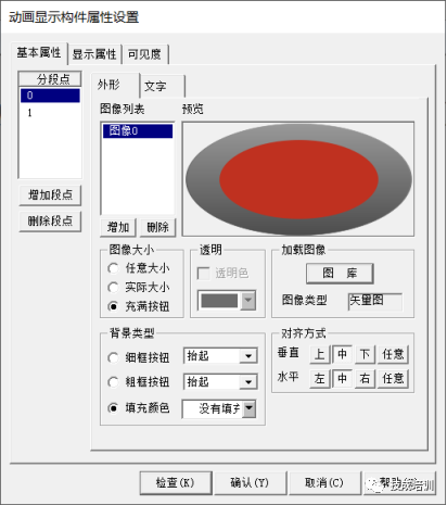
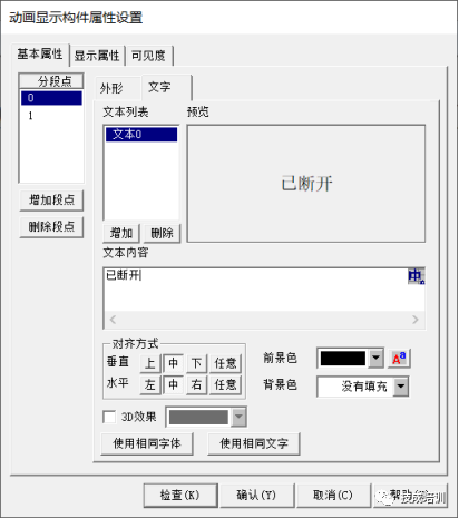
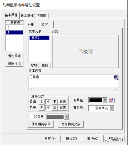
Toolbox – Animation Display – Basic Properties – Select Text Corresponding to States 0 and 1
04Online Simulation Effect Demonstration
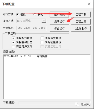
Step 1: (Download Configuration – Select Simulation Mode – Click Project Download – Then Click Start Running)
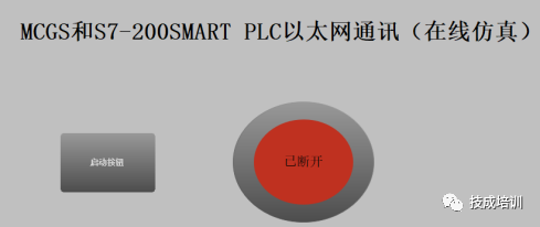
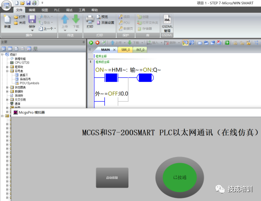
Step 2: (Press the Start Button, PLC M0.0 contact action becomes normally closed to connect output Q0.0)
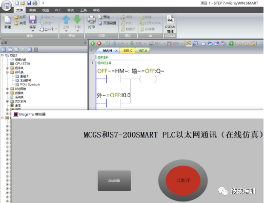
Press the Start Button again, PLC M0.0 contact action becomes normally open while disconnecting Q0.0
Did you learn anything? 
Article Source: Original from Jicheng Training Network, Author: Xu Chenshuang; Reprinting without authorization is prohibited, violators will be prosecuted!
Fan Exclusive
【Full Set of Siemens Materials】

Effortlessly achieve WinCC pop-up following mouse click position function!
2024-04-16
Method for Indirect Addressing of Siemens S7-200smart
2024-04-13

How to Modify Touch Screen When Siemens S7-200smart PLC IO Channel is Broken?
2024-04-11

Detailed Explanation of Configuration for Position Axis of Siemens S7-1200 PLC, Guaranteed You Can Understand!
2024-04-09
How to Use Kunlun Tongtai Configuration Software (MCGSPro) to Simulate Communication with FX5U, Very Detailed!
2024-04-04