▼Click the card below to follow our public account for more exciting content▼

Welcome to follow the 【Master Microcontroller and Embedded Systems】 public account, reply with keywords to get more free videos and materials
Reply with 【Join Group】, 【Microcontroller】, 【STM32】, 【Hardware Knowledge】, 【Hardware Design】, 【Classic Circuits】, 【Thesis】, 【Graduation Project】, 【3D Packaging Library】, 【PCB】, 【Capacitor】, 【TVS】, 【Impedance Matching】, 【Data】, 【Termination Resistor】, 【Keil】, 【485】, 【CAN】, 【Oscillator】, [USBCAN]、【PCB】, 【Smart Bracelet】, 【Smart Home】, 【Smart Car】, 【555】, 【I2C】, 【Huawei】, 【ZTE】, etc……
STM32 Debugging Steps
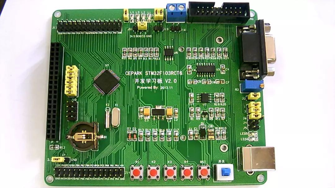
Before debugging, first short the 2-3 pins of jumper J9, short the right two pins of jumper J4, short jumper J5, short J8, short the 1-2 pins of J2, and the 3-4 pins.
Connect the Jlink to the learning board, USB extension cable to the learning board, and serial port extension cable to the learning board (or USB to serial cable to the learning board).
At this time, the LED lights LED5 and LED6 should be lit. If not, it indicates that there is a problem with the board.
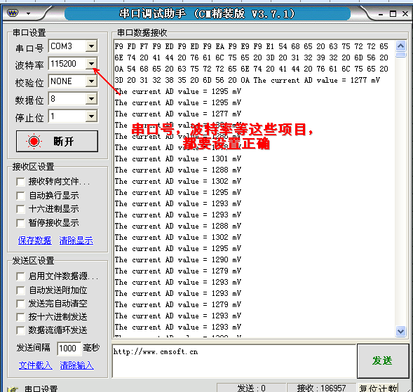
Open the serial assistant and set it as follows:
1. Open J-Flash ARM V4.02 from the desktop as shown.

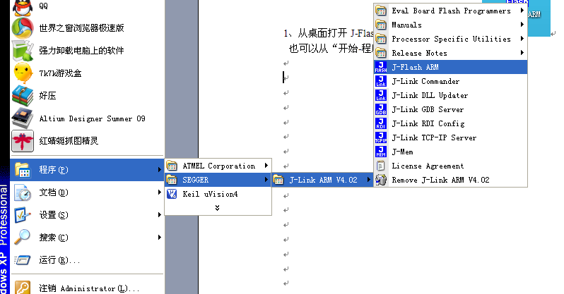
You can also open J-Flash ARM in the following order.
“Start → Program → SEGGER → J-Link ARM V4.02 → J-Flash ARM”, as shown below.
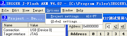
2. After opening J-Flash ARM, first set the chip options, open Options → Project settings as shown below.
A window as shown below will appear, follow the steps shown in the image to set it up
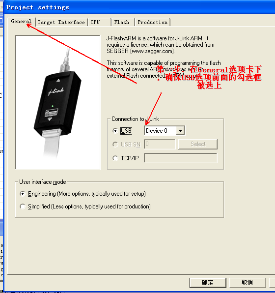
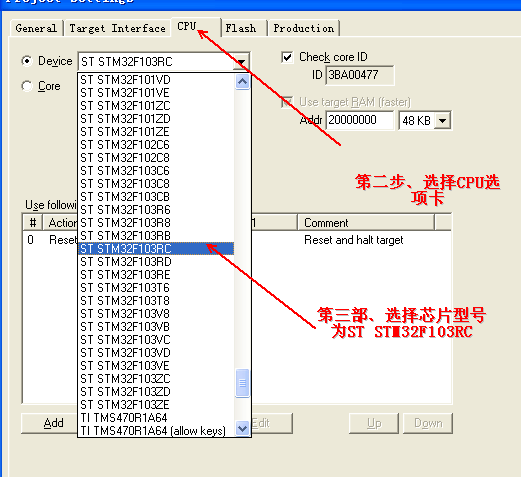
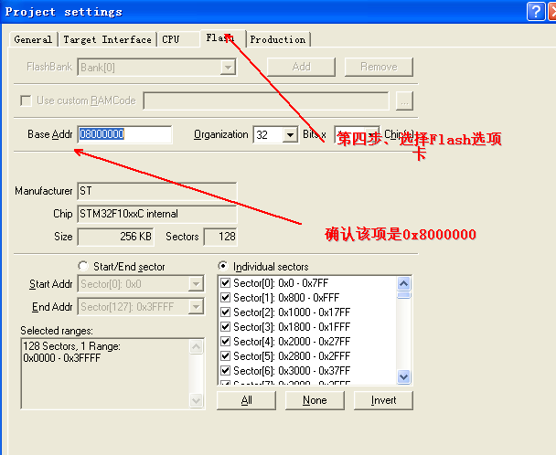
After the setup is complete, click “OK” to save the settings.
3. Select the programming file.Click File → Open, as shown below,
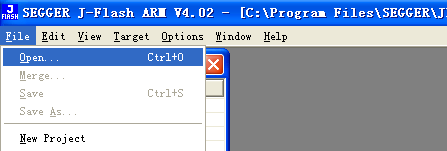
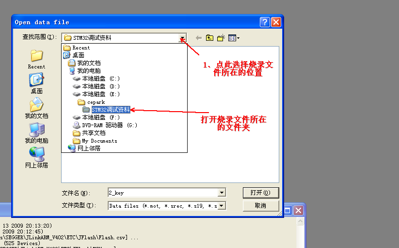
A window as shown below will appear,
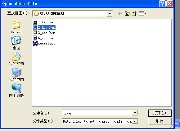
Follow the instructions in the image below to operate,
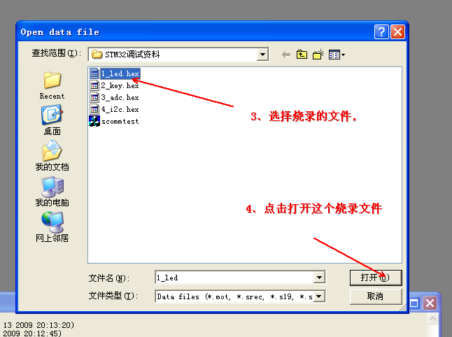
Then the opened file will be displayed, as shown below
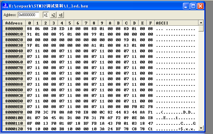
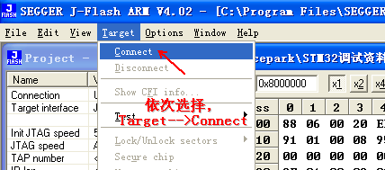
4. If this is the first time connecting the jlink to the learning board, follow the operation shown below
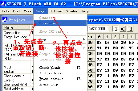
If this is not the first time connecting to the learning board, follow the operation shown below
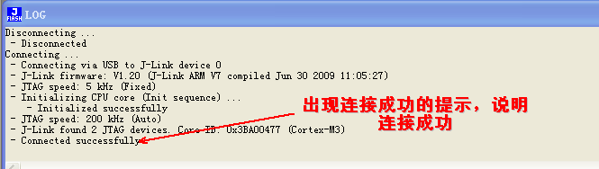
After a successful connection, there will be a prompt as shown below; otherwise, it indicates that there is a connection problem between the board and jlink
5. Program the firmware, follow the operation shown below
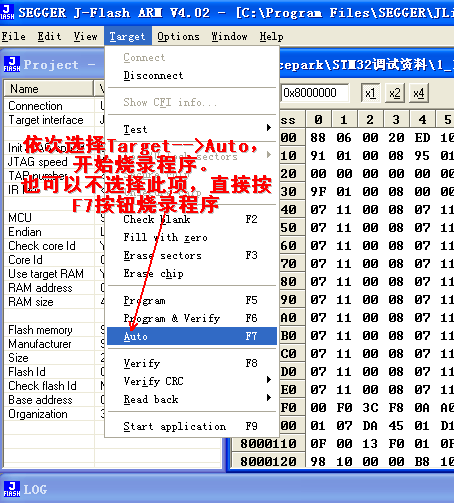
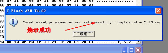
6. After successful programming, press the RST button on the learning board (the button on the far right of the learning board), at this time, 4 LEDs (LED1-LED4) will light up, indicating that the programming was successful, and the LED circuit soldered is also correct.

E N D



Welcome to follow my public account, reply with 【Join Group】 or scan the QR code to add me as a friend, limited-time free entry to the technical exchange group, and you can also join my knowledge circle for free.

 Recommended Reading
【Album】Device Selection
【Album】Microcontroller
【Album】Experience Sharing
【Album】STM32
【Album】Hardware Design
【Album】Software Design
【Album】Open Source Projects
【Album】Career Development
Thank you everyone for reading, if you like it
please like and “view” it, or share it to your circle of friends.
Click to jump to the original text, limited-time free entry to our knowledge circle (add friends to get free coupons)