Introduction to J-Link, DAPLink, ST-Link, and J-Link OB

Click on the “Xuan Ge Talks Chips” above to follow and learn more exciting content!

There are too many types of microcontroller debuggers on the market, such as J-Link OB, DAPLink, J-Link PRO, ST-Link, etc.
Today, we will introduce and sort them all out, and later we will create a comprehensive debugging tool.

1. Segger’s Official J-Link Family

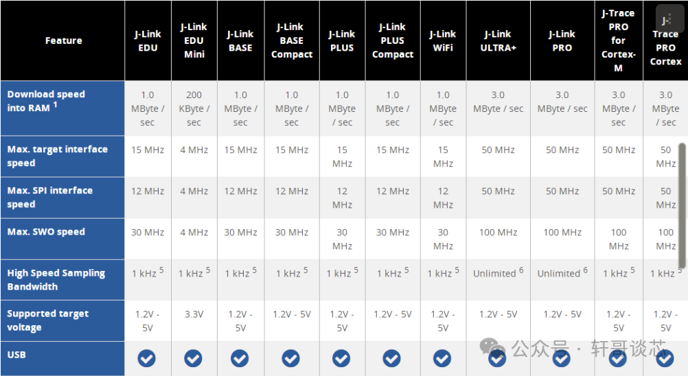
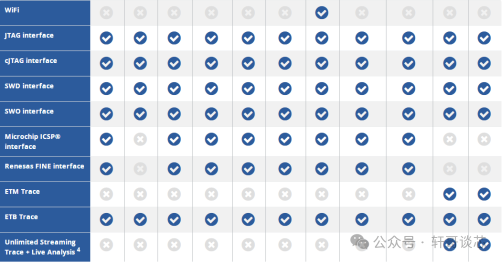
First, let’s take a look at the official J-Link. Its speed and performance are undoubtedly the best, along with various additional features such as support for network and Wi-Fi. Using Segger’s J-Link makes it very convenient to use their various debugging software. Currently, their debuggers are also quite expensive, for instance, the J-Link PRO imported is over 8000. In comparison, the J-Link EDU offers the best cost-performance ratio, with comprehensive features at a more affordable price, although the speed is average, it is sufficient for use.
The product series and function comparison are as follows:

Introduction to J-Link, DAPLink, ST-Link, and J-Link OB

Introduction to J-Link, DAPLink, ST-Link, and J-Link OB

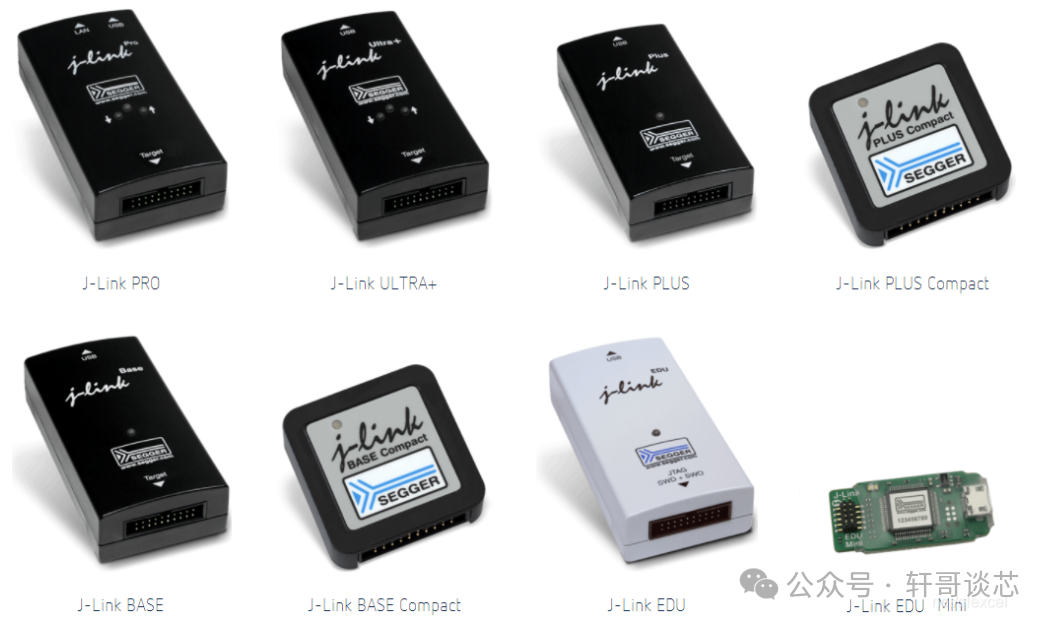
Their appearances are shown in the following picture, a family photo of SEGGER debuggers:

Introduction to J-Link, DAPLink, ST-Link, and J-Link OB

2. DAPLink (CMSIS-DAP)

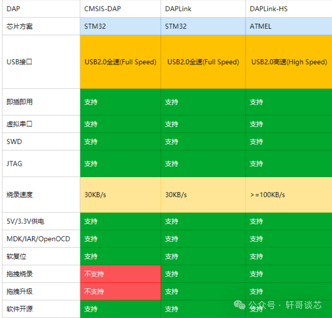
DAPLink was previously known as CMSIS-DAP. Its hardware and software are both open-source (open-source GitHub URL: https://github.com/ARMmbed/DAPLink), and it supports programming and debugging applications running on ARM Cortex microcontrollers.
The source code of DAPLink is open-source, allowing you to modify the code, speed it up, add features, etc. For example, it can be modified for wireless debugging, which is the source of the wireless debuggers sold on certain platforms.
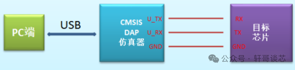
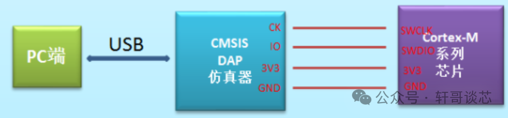
It connects to the target MCU’s SWD or JTAG port. Since implementing DAPLink only requires one MCU and very few peripheral devices, many official development boards have integrated DAPLink. The relationships between DAPLink’s serial port functionality and SWD, JTAG mode connections are as follows:
Serial Port:

Introduction to J-Link, DAPLink, ST-Link, and J-Link OB

SWD Debugging:

Introduction to J-Link, DAPLink, ST-Link, and J-Link OB

DAPLink has added drag-and-drop download functionality compared to the original CMSIS-DAP, which essentially uses USB to create a virtual USB drive interface. When we drag a Bin or Hex file into the USB drive, it automatically converts to the SWD interface for programming onto the target board.
Additionally, DAPLink has added a CDC-based virtual serial port feature, which enumerates a serial port on the computer, similar to chips like PL2303 or FT232, allowing for log output and serial debugging directly.
The firmware of DAPLink supports USB drive upgrades. You just need to ground nRST, insert DAPLink, and a USB drive will appear on the PC. Simply drag the new firmware (Hex or Bin file) into the USB drive to complete the firmware upgrade. This is because DAPLink implements a bootloader with USB drive functionality, making firmware upgrades convenient.
DAPLink supports mainstream IDE software such as Keil, IAR, openocd, etc. The most convenient part is that it requires no driver installation, just plug and play.
Unfortunately:
Since the native DAPLink project is based on full-speed USB 2.0, the programming download speed will be limited by USB. However, since DAPLink is open-source on GitHub, we can port it to microcontrollers with high-speed USB capabilities.

Introduction to J-Link, DAPLink, ST-Link, and J-Link OB

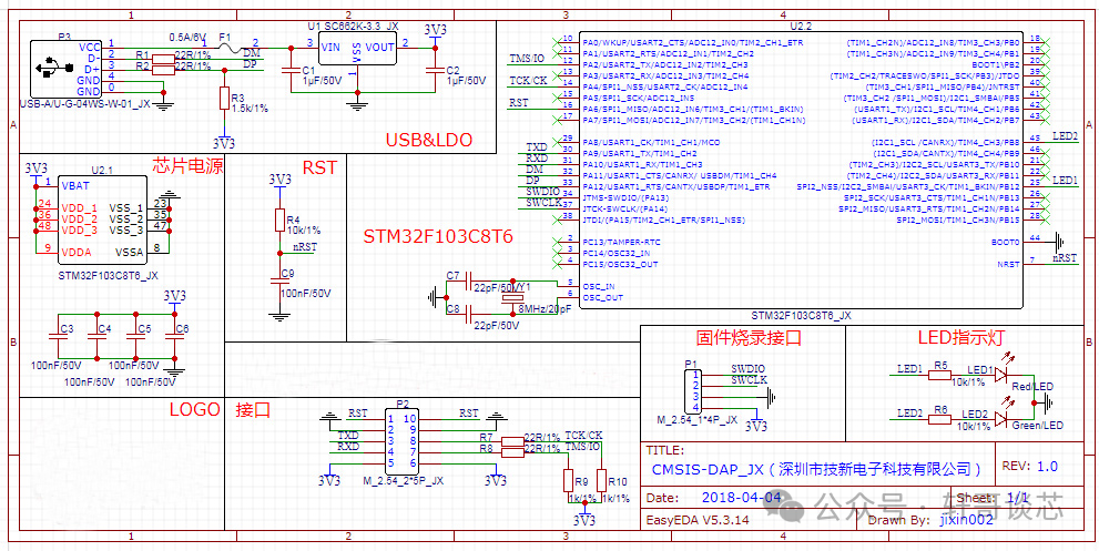
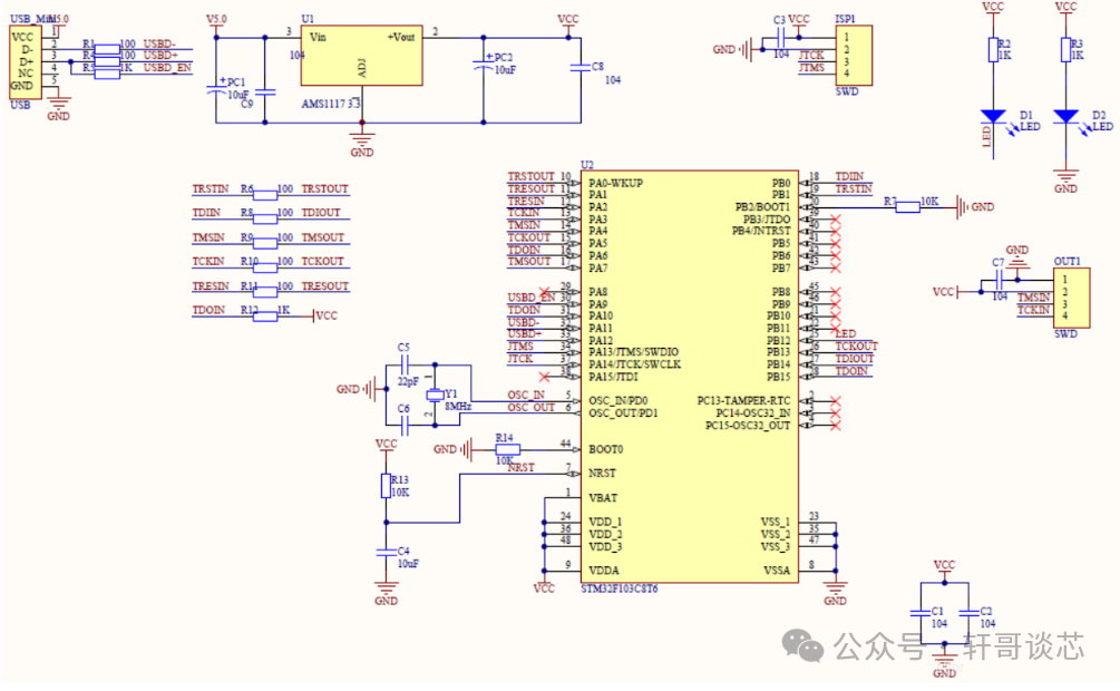
Here is the DIY circuit diagram:

Introduction to J-Link, DAPLink, ST-Link, and J-Link OB

3. J-Link OB

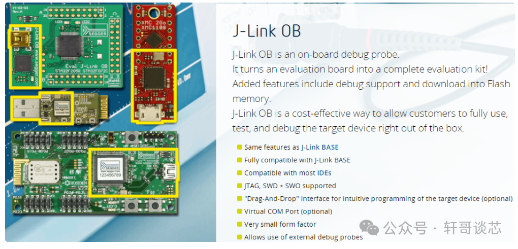
J-Link-OB is a standalone debugging downloader developed by SEGGER, typically designed into evaluation boards of various companies (hence the suffix “OB”).

Introduction to J-Link, DAPLink, ST-Link, and J-Link OB

The schematic is quite simple, basically just a pair of IO ports simulating the SWD protocol, plus a USB interface:

Introduction to J-Link, DAPLink, ST-Link, and J-Link OB

ST-Link is ST’s own J-Link OB solution. It can also be programmed to turn J-Link OB into ST-Link.
It can be seen that the hardware circuits of DAPLink, J-Link OB, and ST-Link are all minimal circuits of a microcontroller, leading out two ordinary IOs as SWDIO and SWCLK for programming the target microcontroller. The only difference is their firmware. The similarity in hardware determines that their programming performance and other functions are quite similar.
I plan to DIY my own debugger, using a USB HUB to unify it into one interface, supporting serial, CAN, and SWD debugging. Initially, I still want to choose J-Link OB for the following reasons:
  1. J-Link OB can be continuously updated with the J-Link software.
  2. J-Link has RTT functionality, making it easy to port my own log system.
  3. J-Link can work with J-Scope software for higher-speed waveform display, which is very helpful for debugging motor control code.
  4. If J-Link OB is not fast enough, I can directly upgrade to J-Link V9.
    More DIY materials can be downloaded by clicking Read the Original.

Previous Recommendations

Using Capacitors to Transport Charges for BMS Balancing

A Few Insights on Bluetooth Development

1. The History of Bluetooth Development

Second Article: Detailed Explanation of Bluetooth Frequency Bands, Frequency Hopping, and Link Parameters

Third Article: How Bluetooth Broadcasting Achieves Diversity?

How to Use Current Compensation Open Circuit Voltage Method for SOC

Six Major Reasons for MOSFET Failure

How BMS Discharge MOSFETs Break Down Under Overvoltage?

End of Article. If you find it well-written, pleasegive a thumbs up or “read it“. It would be best tostar itbecause WeChat’s rules have changed a lot. Thank you for reading..

Leave a Comment