Click on the above  “Chuangxue Electronics” to follow and easily learn electronic knowledge.
Speaking of Freescale’s Kinetis, it has been on the market for nearly three years (I have been dealing with it for exactly two years, haha). The market has proven that its performance is reliable (its leading position in automotive electronics is not to be underestimated, although Renesas took the top spot after merging with NEC, Freescale’s technical foundation is still trustworthy). However, many people often encounter the issue of locked chips when developing with Kinetis (this can indeed be quite troublesome, especially with the early versions of Kinetis where unstable voltage could lead to flash being locked, which is a design consideration by Freescale for reliability). Regarding this, some friends have previously asked me, and there are many opinions online, each with its rationale, so I will sift through the solutions available online and list a few reliable methods here (of course, if you want to know the reason behind it, you can refer to the Security chapter in the Kinetis official Reference Manual) for everyone’s reference:
First, let’s talk about the reasons for chip locking (this is my principle for solving problems; I always want to know why, cough cough, a bit stubborn). I categorize it into the following reasons:
1) Unstable power supply causing the chip to lock, which is a self-protection mechanism of the chip; this is undeniable and related to the hardware environment;
2) Non-standard behavior during debugging; the most common mistake made by beginners is hot-plugging the debugger, which is a bad habit. In fact, many cases of chip locking are caused by this. I have debugged Kinetis in a standard mode for two years and have only locked it twice, both of which were successfully unlocked;
3) Excessively high soldering temperature while soldering Kinetis can damage the chip internally; in such cases, it is generally very difficult to unlock. It is recommended to keep the temperature around 300 degrees during soldering and definitely not exceed 400 degrees;
4) Intentionally locking the chip, which is necessary for mass-produced products; Kinetis provides a reliable intellectual property protection mechanism;
5) Long connection lines between the debugger and the target chip can cause timing mismatches or instability, leading to unintended erasure of the chip’s internal security memory (0x400~0x40F), thus locking the chip;
Having discussed the locking issue, let’s move on to how to unlock it. The principle of unlocking is quite simple: once the chip is locked, the debugger is not allowed to read or write to its internal flash. However, Kinetis still leaves us a way out (otherwise, there would be no hope, so it’s important to always leave a way out, haha). After the chip is locked, it can still perform a “mass erase” through the debugger, which erases the entire chip. After erasing, it can restore its initial state and continue reading and writing. However, if the chip is locked at the highest level, meaning “mass erase” is also disabled, then it is basically hopeless, but such cases are rare. Below are currently effective unlocking methods.
The most commonly used method is the Jlink unlocking method. Currently, there are mainly two debuggers that support “mass erase” well: one is Jlink, and the other is PGO’s USBDM. Both of these debuggers provide relatively simple and user-friendly full chip erasing capabilities:
1) There are three methods to unlock using Jlink, one of which is very simple: connect the hardware platform, then open J-Link Commander and enter “unlock kinetis” in the cmd environment. However, this method only applies to cases where the chip is simply locked. If the chip is locked at a higher level, this method may not be very effective. However, since this method is simple, it is recommended to try it first;
2) The second method for Jlink unlocking is more complex, so I have packaged the unlocking methods and related files and uploaded them to the attachments below this blog. It is recommended to download and take a look;
3) Open the Jlink’s built-in J-Flash ARM to unlock, using its built-in Erase Flash option. For software usage, refer to one of my earlier articles at http://www.eeskill.com/article/id/36563;
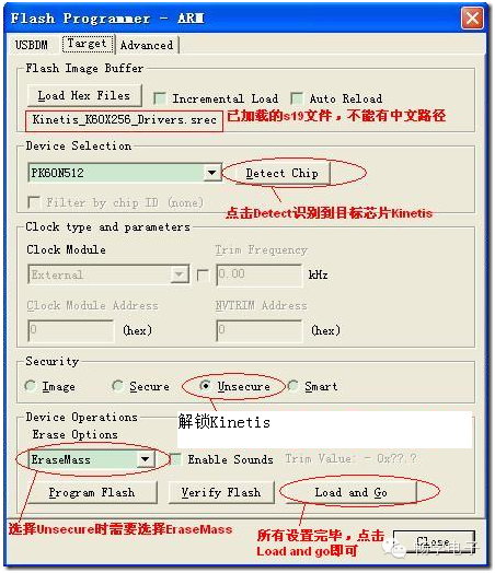
4) USBDM unlocking is now a popular debugger on the market (most versions of Kinetis debuggers on Taobao are based on USBDM, while the rest are based on OSBDM), thanks to the open-source spirit of PGO. The hardware is simple, the firmware code is open-source, and the functionality is powerful, so it’s no surprise it’s popular. However, unfortunately, it currently only supports CodeWarrior. If it can be expanded to IAR, Keil, and other IDEs in the future, it would be even more popular. The unlocking method for USBDM is also quite simple: after installing the USBDM software suite and connecting the hardware platform, open the USBDM’s built-in ARM Programmer programming software, then select any compiled and connected s19 file in the “Target” tab, click “Detect Chip”, and finally select as shown in the image below in “Security” and “Device Operations”, then click “Load and Go” to unlock;
4) Additionally, you can also unlock through some development environments; interested parties can explore this themselves.
> > > > > > > > > > > > > > > > > > > > > > > > > > > > > > > > > > > > > > > > > > > > > > > > > > > > > >
==> Visit www.eeskill.com to learn more!