Introduction to JLINK RTT: Replacing UART with RTT

In microcontroller development, printing debug information usually relies on serial ports. However, if no serial port is reserved, the RTT (Real-Time Transfer) function of the JLINK debugger can serve as an alternative. RTT enables real-time communication between the target device and the debugging host through the JLINK debugger, supporting log output and data collection while having minimal impact on system performance.

1. Install JLink Driver

Download link: https://www.segger.com/downloads/jlink/. After purchasing the JLink driver, the seller usually provides the JLink driver program. Once the driver installation is complete, you can download the debugging program.
Introduction to JLINK RTT: Replacing UART with RTT
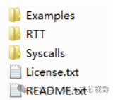
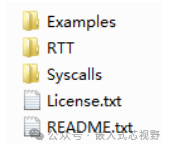
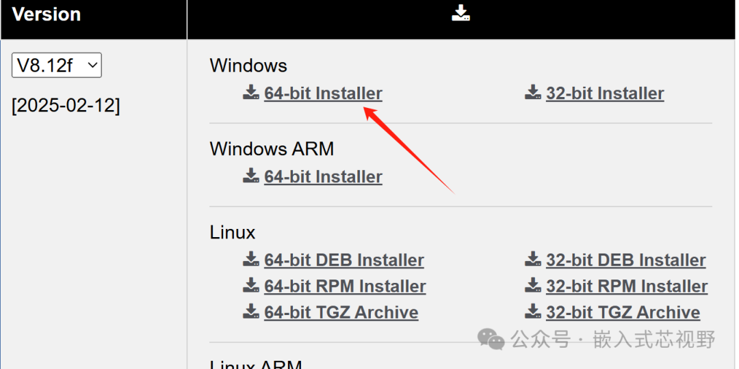
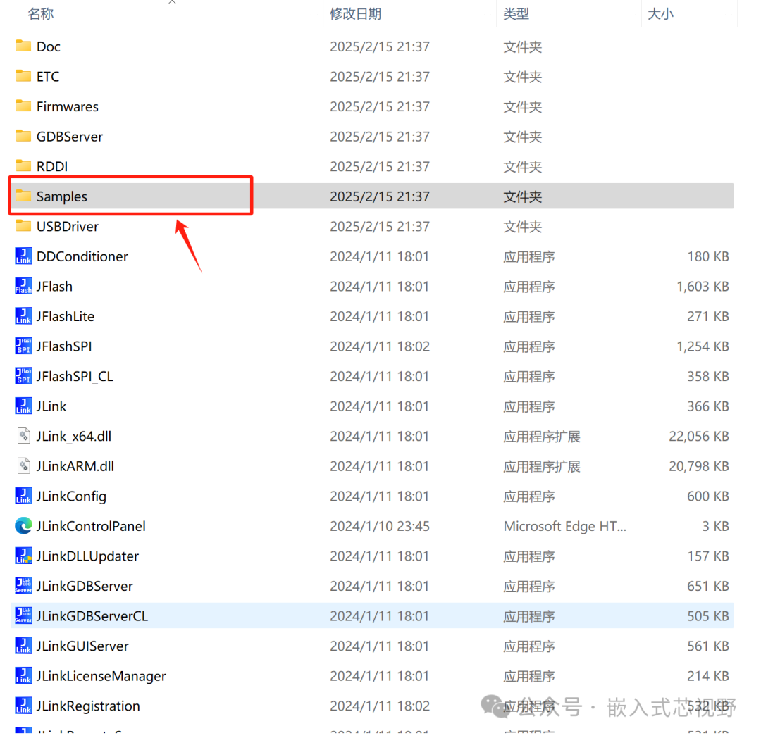
To use the RTT function of JLink, you need to download the complete JLink package from the official website. The latest version is V8.12f, but other versions are also acceptable. After downloading, you can install it directly. Once installed, you will see the following content in your installation directory:
Introduction to JLINK RTT: Replacing UART with RTT

2. Porting RTT

2.1 Porting RTT Component in MDK

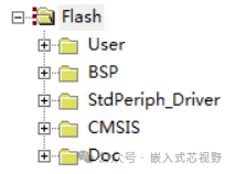
(1)The example project is grouped as follows:
Introduction to JLINK RTT: Replacing UART with RTT

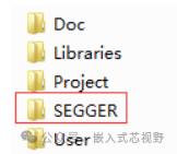
(2)Create a new SEEGER folder in the project directory and add all the contents of the RTT component.
Introduction to JLINK RTT: Replacing UART with RTT

The added content is as follows:

Introduction to JLINK RTT: Replacing UART with RTT

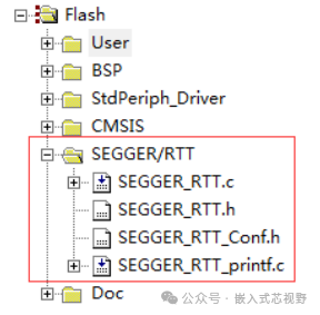
(3)Add the RTT component to the MDK project. Add all four files from the RTT folder in step 2 to the MDK project. The result after adding is as follows:
Introduction to JLINK RTT: Replacing UART with RTT

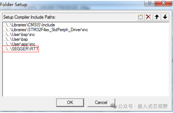
(4)Finally, add the path.

Introduction to JLINK RTT: Replacing UART with RTT

2.2 Porting RTT Component in IAR

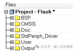
(1)The example project is grouped as follows:
Introduction to JLINK RTT: Replacing UART with RTT

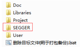
(2)Create a new SEEGER folder in the project directory and add all the contents of the RTT component.
Introduction to JLINK RTT: Replacing UART with RTT

The added content is as follows:

Introduction to JLINK RTT: Replacing UART with RTT

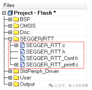
(3)Add the RTT component to the IAR project. Add all four files from the RTT folder in step 2 to the IAR project. The result after adding is as follows:
Introduction to JLINK RTT: Replacing UART with RTT

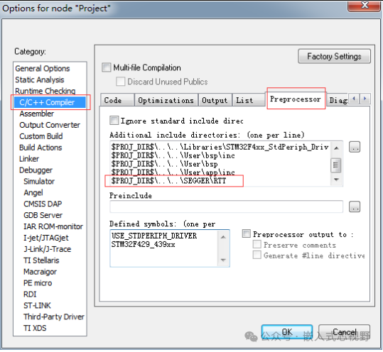
(4)Finally, add the path.

Introduction to JLINK RTT: Replacing UART with RTT

3. Using RTT (RTT Viewer)

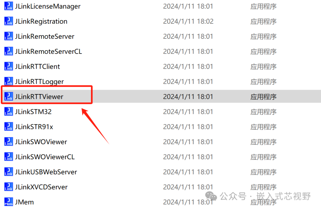
The computer software for RTT, JLINK RTT Viewer, is located in the installation directory of the JLINK driver on your computer.

Step 1: After downloading the program to the board, power it back on.

Step 2: Open the RTT Viewer software; the effect is as follows:
Introduction to JLINK RTT: Replacing UART with RTT

Introduction to JLINK RTT: Replacing UART with RTT

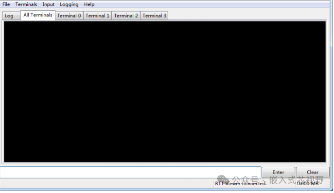
Step 3: The popped-up interface looks like this:
Introduction to JLINK RTT: Replacing UART with RTT

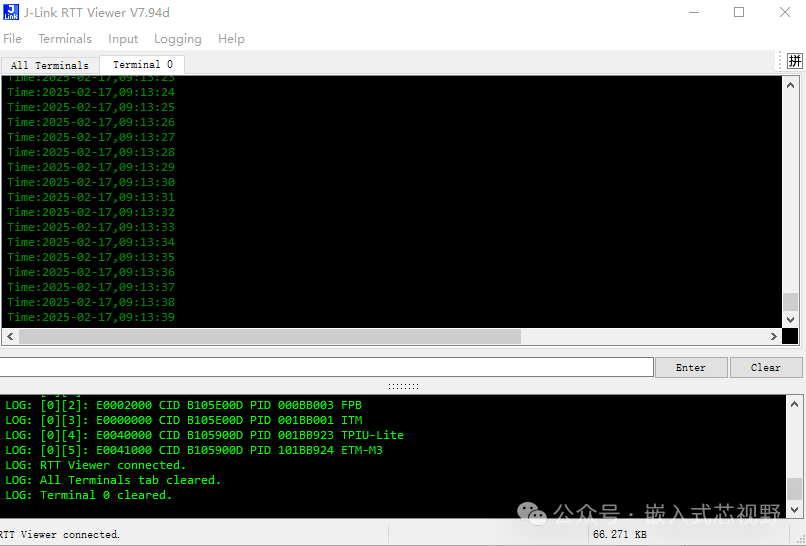
Step 4: Opening this software will connect automatically. If it doesn’t connect, click the menu File->Connect

to connect. You can select the Log option to view:
Introduction to JLINK RTT: Replacing UART with RTT

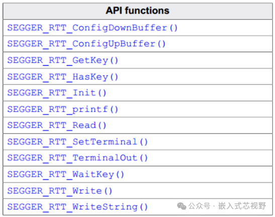
4. RTT API Function Description

RTT supports the following APIs:
Introduction to JLINK RTT: Replacing UART with RTT
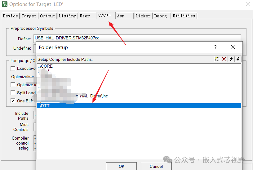
(4)Of course, remember to add the<span>RTT</span> header file path and add the RTT source code to the project.
Introduction to JLINK RTT: Replacing UART with RTT
(5)Open the<span>JLinkRTTViewer.exe</span> in the JLink installation directory.
Introduction to JLINK RTT: Replacing UART with RTT
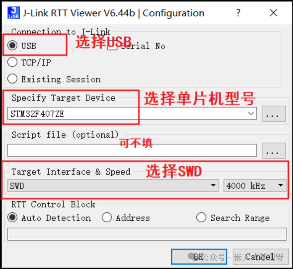
(6)RTT settings as follows:
Introduction to JLINK RTT: Replacing UART with RTT

Leave a Comment