Implementing PID Control for Motors Using STM32
The PID control algorithm is quite old yet widely used, ranging from controlling the temperature of a kettle to managing the flight attitude and speed of drones. In motor control, the PID algorithm is particularly common.
1. Position PID
1. Calculation Formula
In motor control, we output a PWM duty cycle value to the motor.
Without further ado, here is the basic formula for position PID:
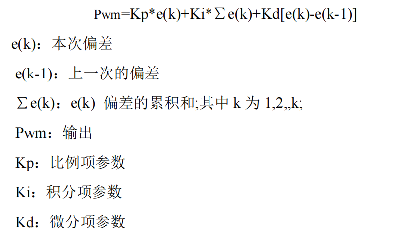
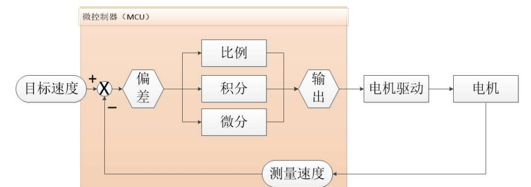
The control flowchart is as follows:
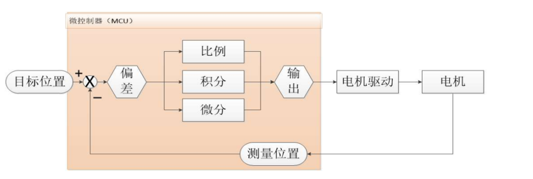
The target position in the above diagram can generally be changed through programming via buttons or switches, while the measured position is obtained by collecting encoder data through the STM32.
The difference between the target position and the measured position represents the current system deviation. This deviation is sent to the PID controller for calculation and output, which then controls the motor’s rotation via power amplification to reduce the deviation, ultimately reaching the target position.
2. C Language Implementation
How do we implement the theoretical analysis and control schematic in C language? This is an interesting and practical process. The code for implementing position PID in C is as follows:
int Position_PID (int Encoder,int Target){static float Bias,Pwm,Integral_bias,Last_Bias;Bias=Target- Encoder; // Calculate deviationIntegral_bias+=Bias; // Calculate integral of deviationPwm=Position_KP*Bias+Position_KI*Integral_bias+Position_KD*(Bias-Last_Bias);// Basic PID formulaLast_Bias=Bias; // Save last deviationreturn Pwm; // Output}The input parameters are the encoder’s position measurement and the target position for control, while the return value is the motor control PWM (now looking back at the control flow chart should be clearer).
The first line defines the relevant internal variables.
The second line calculates the position deviation by subtracting the target value from the measured value.
The third line accumulates to find the integral of the deviation.
The fourth line uses the position PID controller to determine the motor PWM.
The fifth line saves the last deviation for the next call.
The last line is the return.
2. Incremental PID
1. Calculation Formula
Velocity closed-loop control measures the motor’s speed information based on the number of pulses obtained per unit time (using the M method for speed measurement) and compares it with the target value to determine the control deviation. The deviation is then controlled through proportional, integral, and derivative actions to bring it towards zero.
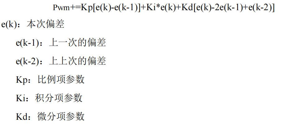
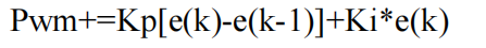
In our speed control closed-loop system, only PI control is used, thus simplifying the PID controller to the following formula:
The control flowchart is the same as for the position PID.
The target speed in the above diagram can generally be changed through programming via buttons or switches, while the speed measurement, as mentioned in the encoder section, is obtained by periodically collecting encoder data and resetting it.
The difference between the target speed and the measured speed represents the current system deviation. This deviation is sent to the PID controller for calculation and output, which then controls the motor’s rotation via power amplification to reduce the deviation, ultimately reaching the target speed.
2. C Language Implementation
How do we implement the theoretical analysis and control schematic in C language? This is an interesting and practical process. The code for implementing incremental PI in C is as follows:
int Incremental_PI (int Encoder,int Target){static float Bias,Pwm,Last_bias;Bias=Encoder-Target; // Calculate deviationPwm+=Velocity_KP*(Bias-Last_bias)+Velocity_KI*Bias; // Incremental PI controllerLast_bias=Bias; // Save last deviationreturn Pwm; // Incremental output}The input parameters are the encoder’s speed measurement and the target speed for control, while the return value is the motor control PWM.
The first line defines the relevant internal variables.
The second line calculates the speed deviation by subtracting the target value from the measured value.
The third line uses the incremental PI controller to determine the motor PWM.
The fourth line saves the last deviation for the next call.
The last line is the return.
3. The Role of P, I, and D Parameters
The performance indicators of an automatic control system primarily include three aspects: stability, rapidity, and accuracy.
Stability: A system is considered stable if the controlled variable eventually aligns with the given expected value over time after being subjected to external influences, which we generally refer to as system convergence.
If the controlled variable increasingly deviates from the given value over time, the system is considered unstable, which we generally refer to as system divergence. A stable system is necessary to complete automatic control tasks, making system stability a prerequisite for normal operation of the control system.
A stable control system should see the initial deviation of the controlled variable from the given value gradually decrease and approach zero over time.
Rapidity: Rapidity refers to the duration of the dynamic process of the system. The shorter the process time, the better the system’s rapidity; conversely, a longer process time indicates sluggish response, making it difficult to realize rapid changes in command signals.
Stability and rapidity reflect the system’s performance during the control process. The smaller the deviation from the given value during tracking and the shorter the deviation time, the higher the dynamic precision of the system.
Accuracy: This refers to the deviation of the controlled variable (or feedback quantity) from the given value after the dynamic process concludes. This deviation, known as steady-state error, is an indicator of the system’s steady-state precision, reflecting performance in the later stages of the dynamic process.
In practical production engineering, different control systems have varying requirements for controller performance. For example, balance vehicles and inverted pendulums require high rapidity; slow responses can lead to system loss of control.
In smart home systems, such as automatic window and door opening systems, rapidity requirements are lower, but stability and accuracy are crucial, necessitating strict control over overshoot and static error.
Copyright Statement: This article is an original piece by CSDN blogger ‘青春草原晖太郎’, following the CC 4.0 BY-SA copyright agreement. Please include the original source link and this statement when reprinting.
Original link:
https://blog.csdn.net/weixin_43811044/article/details/127956227


↓↓ Click to Read the Original, or Scan the QR Code Above to Apply for Free