MAKER:Makertronics/Translated By:Fun Without End
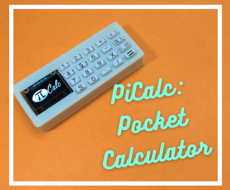
Hello everyone! Today is Pi Day of 2022. Let’s introduce a Pi calculator!
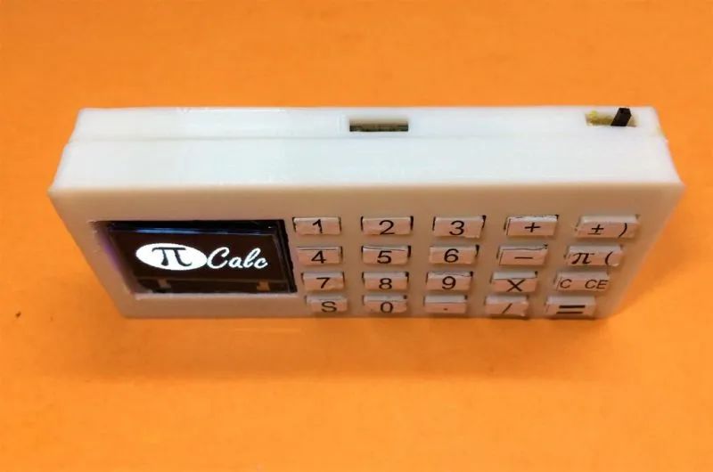
This is a calculator made with Pico, which I call PiCalc. This tiny calculator may be small in size, but it has all the necessary functions. It supports decimal numbers and expressions with parentheses priority. Just pull it out of your pocket when needed!Features1. By default, the execution priority is similar to the BODMAS rule.
2. The right-side keys have dual functions, and the bottom left corner has a shift key to switch the functions of the right-side keys.
For example: To use the left parenthesis 【(】, first click the 【S】 key in the bottom left corner, and then click the second key at the top of the last column. The left key in the last column can be used directly without any shift key switch, but to use the keys on the right, you need to press the shift key first.
3. 【C】 means clear a single digit, and 【CE】 means clear all history. If the equation you wrote cannot be processed, “ERROR” will be displayed on the screen, and you can click the clear key to recalculate.

Material List
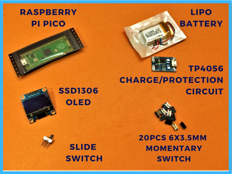
Raspberry Pi Pico x 1 SSD1306 OLED Display x 1 30mmx30mmx4mm Lithium Battery x 1 TP4056 Lithium Battery Charging Circuit x 1 16×3.5mm SMD Momentary Switch x 1 Slide Switch x 1
Keyboard Matrix Principle
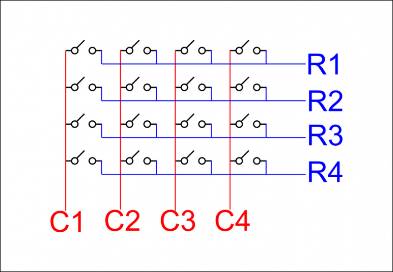
Before making the calculator, we need to understand the input mechanism of the calculator. It is based on multiplexing when inputting from the keyboard. As shown in the figure, the grid of keys is set as terminals and connected by rows and columns.
All right terminals of the keys are connected to the row they are in, and all left terminals are connected to the column they are in, with a total of eight connection points: R1, R2, R3, R4 and C1, C2, C3, C4.
When the user presses a key, we need to find out which column and row the key corresponds to. Therefore, the microcontroller reads the data row by row and then turns on or off the power for each column row by row.
For example, when all input lines are pulled high, the microcontroller reads the input line data. Now let’s assume that the rows are inputs, we will start reading from R1, and the output reading logic will be from C1, C2, C3 to C4. If the voltage at R1 is lower than the others, it will be considered that the key has been pressed.
Circuit and PCB Design
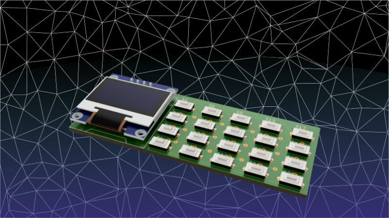
The main circuit of this mini calculator consists of 20 keys arranged in a 4X5 keyboard matrix, then connected to the SSD1306 OLED display and the Pico at the bottom.
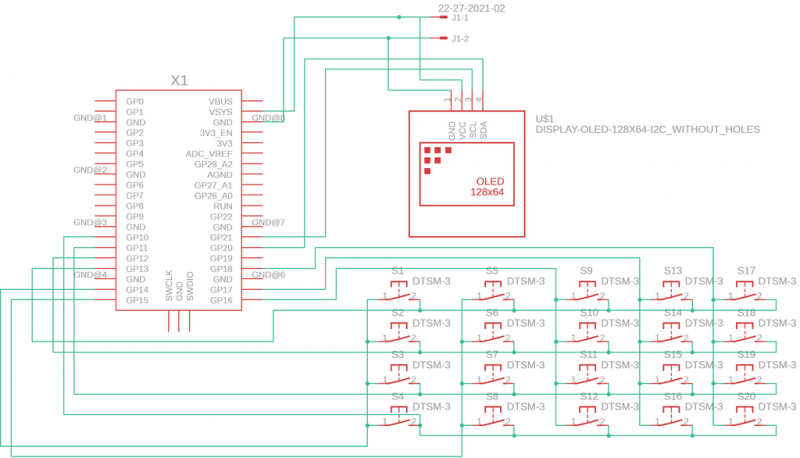
The PCB board is a single-layer design, and the column lines of the keyboard will be directly connected from the outside through solder bridges, with the top layer of the keyboard matrix connected to the bottom of the Pico, where the PCB’s keyboard arrangement is on the left side of the Pico.
If you need a double-layer PCB, you can click the following link https://drive.google.com/file/d/1Mwu2Uq_MpFbF08HvItbTJjrXX-PQ7kn6/view?usp=sharing to skip the following steps.
Making the PCB Board
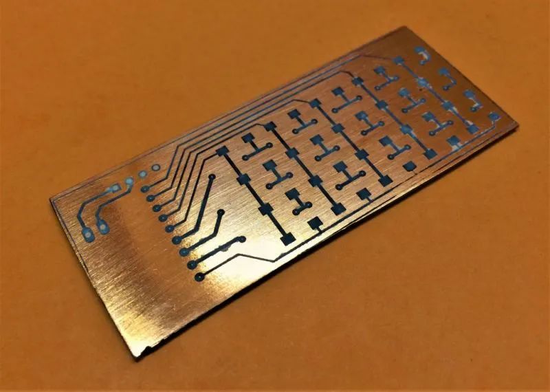
We use the tone agent image transfer method to make the PCB board, which is made of copper-clad board sized 30mm x 78mm.
1. Clean it with high-grit sandpaper to remove the oxide layer.
2. Print the PCB board design on a piece of white paper and align the pattern with the copper plate. Use a heat press or iron to heat it for 5 minutes to transfer the toner from the paper to the copper board.
3. Soak the PCB and paper in warm water to help remove the paper.
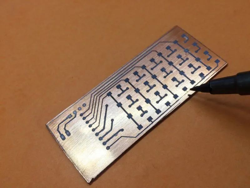
4. If any damage occurs during the process, you can redraw the circuit with a permanent marker.
Etching the PCB Board
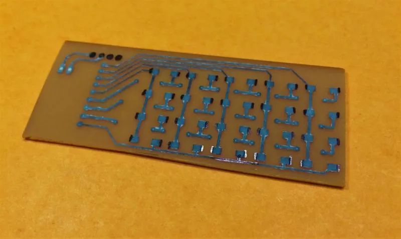
1. Now put the PCB board into the special solution for 5 minutes, then etch away the unwanted copper.
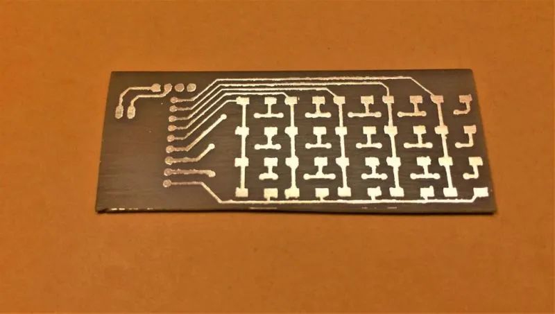
2. Use some acetone to remove the excess toner from the etched PCB board, and the PCB board will be very smooth.
3. Drill some holes with a diameter of 0.8mm in the OLED display for easy connection of the keyboard matrix to the Pico.
Welding Components
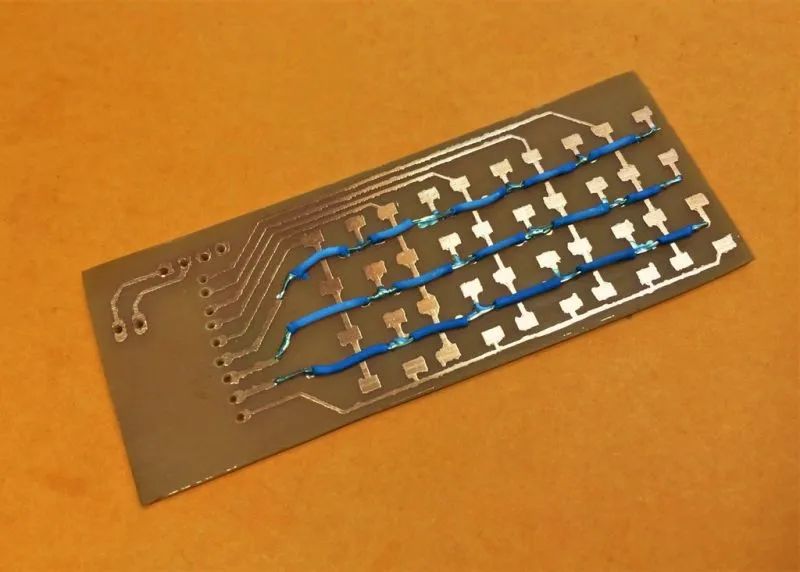
1. Use solder bridges to connect the columns of the keyboard matrix.
2. You only need to solder three rows; the last row is already connected to the copper plate.
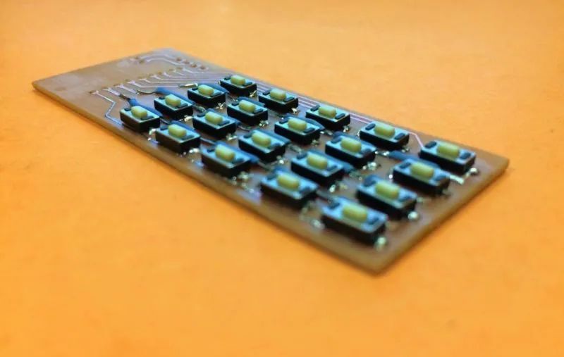
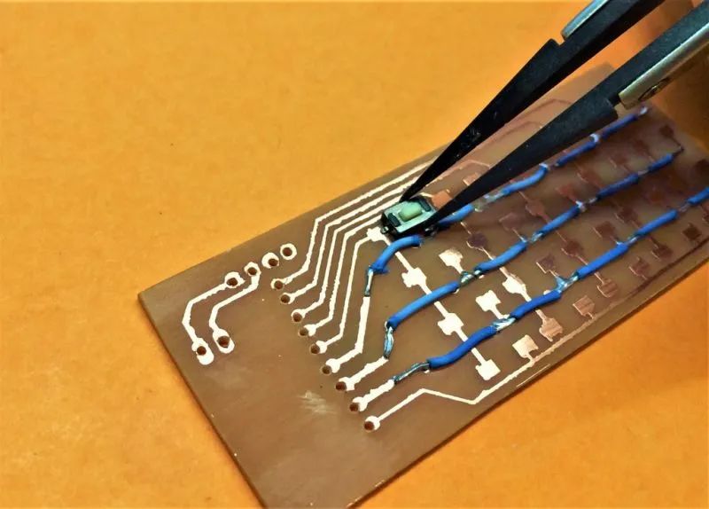
3. Solder the buttons.
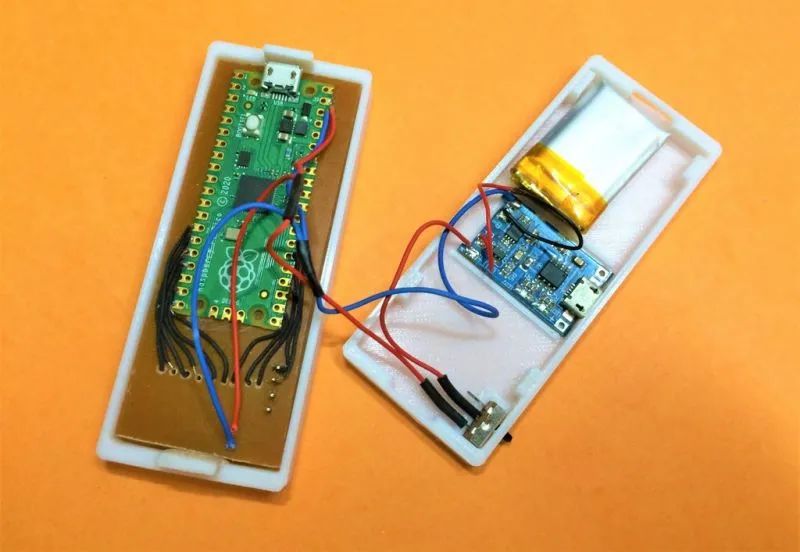
Connect the PCB Board to the Pico
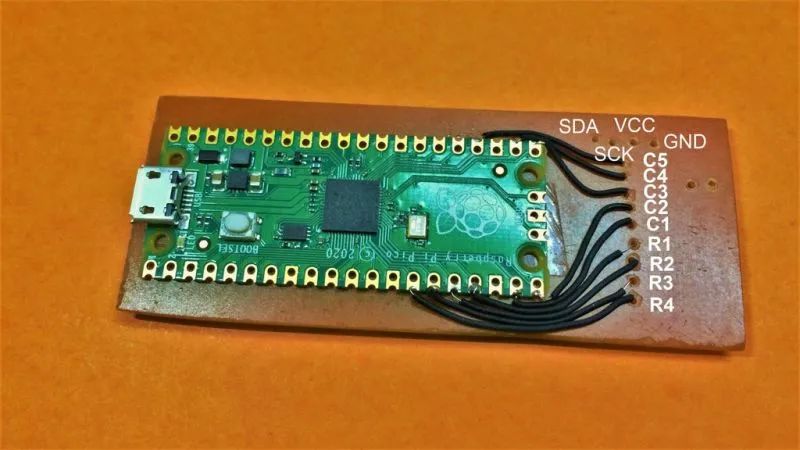
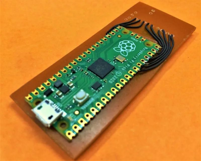
1. As shown in the figure, use double-sided tape to attach the Pico to the back of the PCB board, then solder the Pico’s wires to the holes on the right side.
2. Connect the OLED display, solder it to the holes of the wires, and cover these holes.
Connect the Battery and Charging Circuit
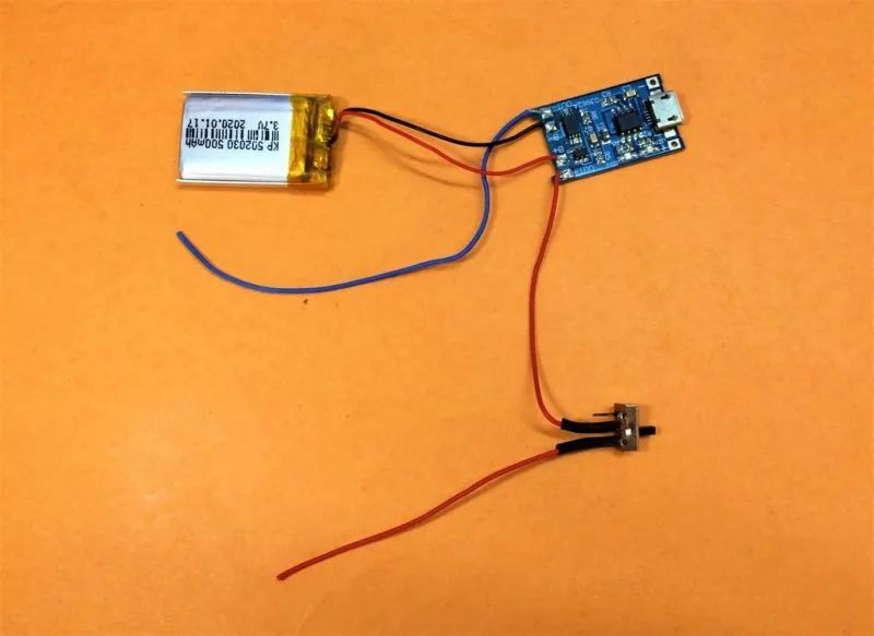
1. Connect the battery and LiPo protection.
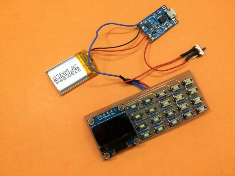
2. Connect the charging circuit TP4056 and switch. 3. Note that the wire ends need to be insulated before placing them into the casing.
Install Thonny IDE
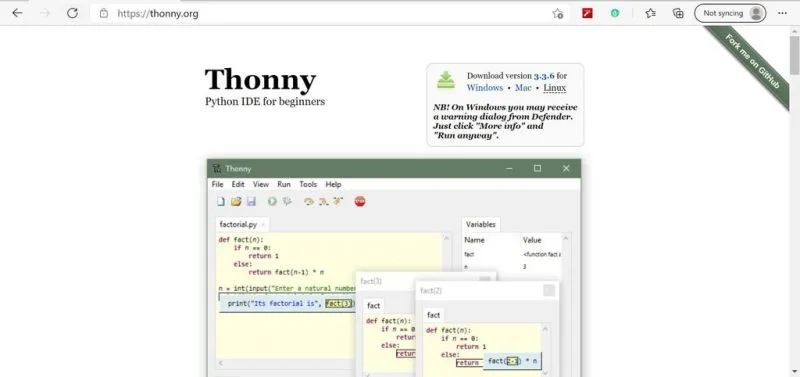
I use the Micropython SDK to program the Pico, completed via Thonny IDE in the Raspberry Pi Linux computer.
1. Please click https://thonny.org/ to obtain the IDE.
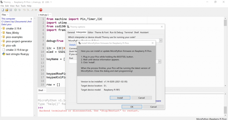
2. After downloading and installing the IDE, connect the Pico to the computer while holding down the boot select button on the Pico to start it in programming mode.
3. A folder will pop up on the screen. Click the link https://www.raspberrypi.com/documentation/microcontrollers/#getting-started-with-micropython to get the micropython firmware and install it into this folder.
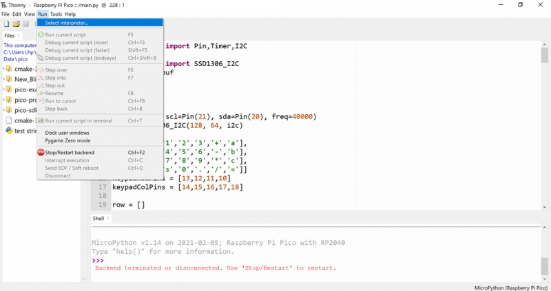
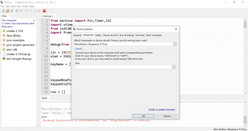
4. You can also execute via Thonny IDE, from Run->Select Interpreter, find the micropython for the Raspberry Pi Pico, and at the bottom of the window, you will see a blue text button “Install or Update Firmware”.
Burning the Pico
Before programming the Pico, the OLED display library needs to be installed.
1. Go to the tools menu to manage packages, search for SSD1306 and install the first one, saving it directly to the Pico.
2. Use the code in the project folder to refresh the PiCalc firmware.
The PiCalc firmware file can be downloaded from this project’s file library: https://make.quwj.com/project/419
Now the calculator function is complete, and all that’s left is to 3D print the casing.
3D Print the Casing
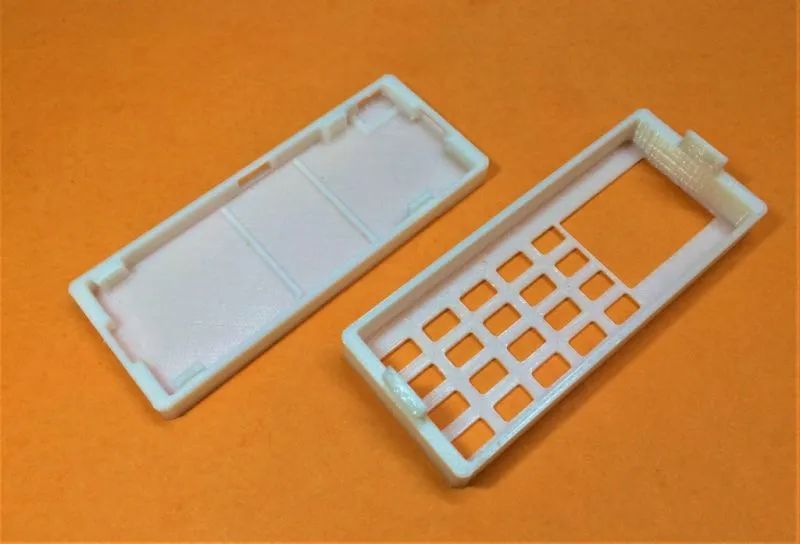
I used the Fusion 360 sync feature from Eagle CAD to transfer the 3D files of the PCB to Fusion 360 and then model it.
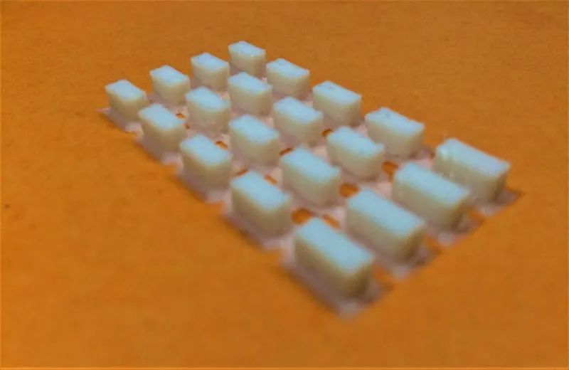
The casing mainly needs to print three parts: the keyboard matrix, the top cover, and the bottom cover.
3D printing uses PLA, with 20% infill, and does not require support.
The 3D printing files can be downloaded from this project’s file library: https://make.quwj.com/project/419
Decorate the Keyboard
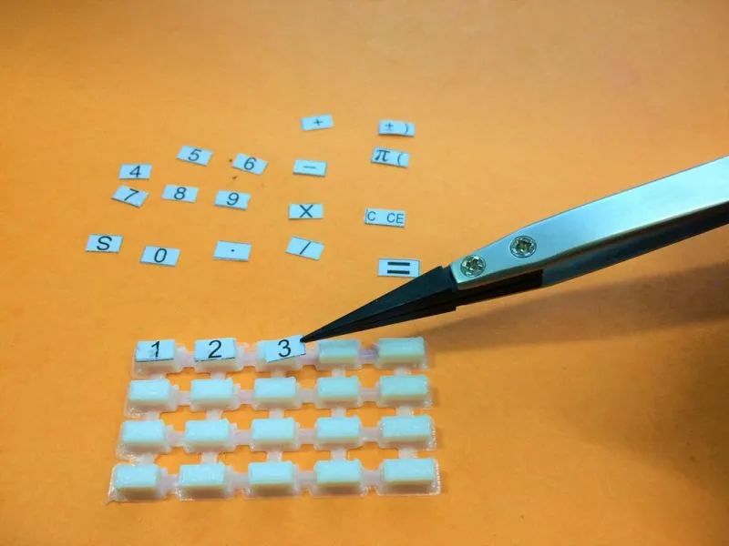
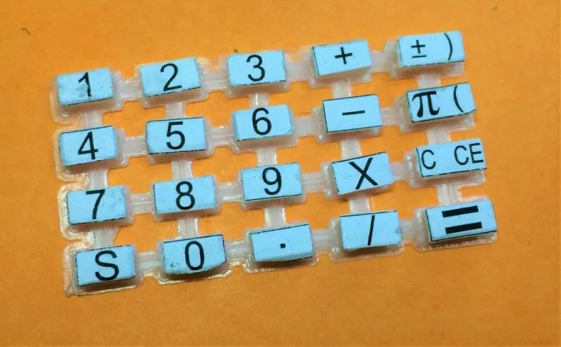
I printed the symbols on the keyboard on paper, cut them out one by one, and pasted them onto the keyboard, paying attention to the size of the symbols.
The keyboard symbol file can be downloaded from this project’s file library: https://make.quwj.com/project/419
Assembly
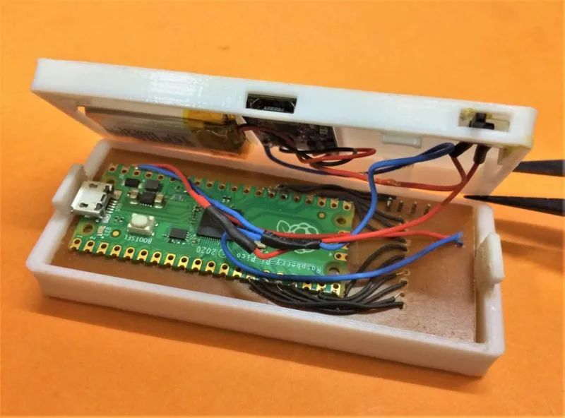
As shown in the figure, this computer has a switch and a TP4056 (charging/protection circuit) cutout, USB slot, and slide switch.
Use double-sided tape to attach the battery; do not use hot melt glue to attach the battery. Insert the keyboard into the grid and install the PCB on top, then snap the casing together.
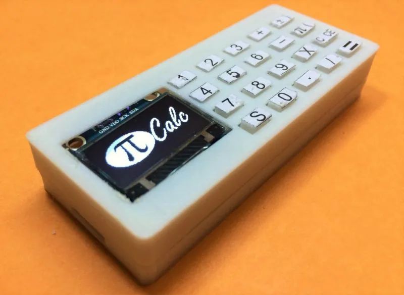
All components combined, this mini calculator is complete.
via instructables.com/PiCalc-Raspberry-Pi-Pico-Based-Pocked-Calculator/
Links in the text can be clicked to read the original text at the end

More Exciting Content