

Microstepping
Example: Using Control BoardArduino Mega to Control Stepper Motor DriverTMC5130-EVAL to Drive the Stepper Motor.
Figure 13. Using Arduino Mega to Control Stepper Motor Driver TMC5130-EVAL
Controller: Arduino Mega 2560 is a microcontroller board based on the ATmega2560. It has 54 digital input/output pins (15 of which can be used as PWM outputs), 16 analog inputs, 4 UARTs (hardware serial ports), a 16 MHz crystal oscillator, a USB connection, a power jack, an ICSP header, and a reset button. It contains everything needed to support the microcontroller; just connect it to a computer with a USB cable or power it with an AC to DC adapter or battery to get started.
Stepper Motor Driver Board: TMC5130 is a fully integrated stepper motor driver and controller system that allows remote control of stepper motors from any microcontroller. It implements all real-time critical tasks in hardware. Once configured, the motor can be driven by giving a target position, commanding a return sequence, or specifying a target speed. Benefits of using TMC5130 include: ease of use, motor precision with 256 microsteps, low motor noise (no noise hidden chopper), sensorless stall detection (stallGuard2), no step loss, dcStep and coolStep, high efficiency with UART or SPI control interface, high voltage range, small form factor, and low component count.
1. Ensure Arduino Mega and TMC5130-EVAL Have Voltage Matching
If the Arduino is a 5V control board, then a resistor on the TMC5130-EVAL must be relocated from position R3 to R8. This sets the logic level of the TMC5130 to +5V.
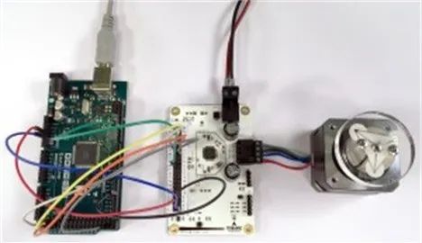
The cable colors in the above image
+5V – > Red
GND – > Blue
SDO – > Yellow
SDI – > Orange
SCK – > White
CSN – > Gray
DRV_ENN – > Black
CLK16 – > Green
Scroll up to view the complete code
#include <SPI.h>
#include “TMC5130_registers.h”
/* The trinamic TMC5130 motor controller and driver operates through an
* SPI interface. Each datagram is sent to the device as an address byte
* followed by 4 data bytes. This is 40 bits (8 bit address and 32 bit word).
* Each register is specified by a one byte (MSB) address: 0 for read, 1 for
* write. The MSB is transmitted first on the rising edge of SCK.
*
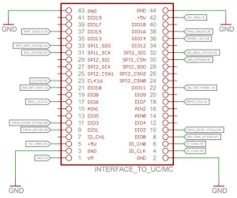
* Arduino Pins Eval Board Pins
* 51 MOSI 32 SPI1_SDI
* 50 MISO 33 SPI1_SDO
* 52 SCK 31 SPI1_SCK
* 25 CS 30 SPI1_CSN
* 17 DIO 8 DIO0 (DRV_ENN)
* 11 DIO 23 CLK16
* GND 2 GND
* +5V 5 +5V
*/
int chipCS = 25;
const byte CLOCKOUT = 11;
// const byte CLOCKOUT = 9; –> Uncomment for UNO, Duemilanove, etc…
int enable = 17;
void setup() {
// put your setup code here, to run once:
pinMode(chipCS,OUTPUT);
pinMode(CLOCKOUT,OUTPUT);
pinMode(enable, OUTPUT);
digitalWrite(chipCS,HIGH);
digitalWrite(enable,LOW);
//set up Timer1
TCCR1A = bit (COM1A0); //toggle OC1A on Compare Match
TCCR1B = bit (WGM12) | bit (CS10); //CTC, no prescaling
OCR1A = 0; //output every cycle
SPI.setBitOrder(MSBFIRST);
SPI.setClockDivider(SPI_CLOCK_DIV8);
SPI.setDataMode(SPI_MODE3);
SPI.begin();
Serial.begin(9600);
sendData(0x80,0x00000000); //GCONF
sendData(0xEC,0x000101D5); //CHOPCONF: TOFF=5, HSTRT=5, HEND=3, TBL=2, CHM=0 (spreadcycle)
sendData(0x90,0x00070603); //IHOLD_IRUN: IHOLD=3, IRUN=10 (max.current), IHOLDDELAY=6
sendData(0x91,0x0000000A); //TPOWERDOWN=10
sendData(0xF0,0x00000000); // PWMCONF
//sendData(0xF0,0x000401C8); //PWM_CONF: AUTO=1, 2/1024 Fclk, Switch amp limit=200, grad=1
sendData(0xA4,0x000003E8); //A1=1000
sendData(0xA5,0x000186A0); //V1=100000
sendData(0xA6,0x0000C350); //AMAX=50000
sendData(0xA7,0x000186A0); //VMAX=100000
sendData(0xAA,0x00000578); //D1=1400
sendData(0xAB,0x0000000A); //VSTOP=10
sendData(0xA0,0x00000000); //RAMPMODE=0
sendData(0xA1,0x00000000); //XACTUAL=0
sendData(0xAD,0x00000000); //XTARGET=0
}
void loop()
{
// put your main code here, to run repeatedly:
sendData(0xAD,0x0007D000); //XTARGET=512000 | 10 revolutions with micro step = 256
delay(20000);
sendData(0x21,0x00000000);
sendData(0xAD,0x00000000); //XTARGET=0
delay(20000);
sendData(0x21,0x00000000);
}
void sendData(unsigned long address, unsigned long datagram)
{
//TMC5130 takes 40 bit data: 8 address and 32 data
delay(100);
uint8_t stat;
unsigned long i_datagram;
digitalWrite(chipCS,LOW);
delayMicroseconds(10);
stat = SPI.transfer(address);
i_datagram |= SPI.transfer((datagram >> 24) & 0xff);
i_datagram <<= 8;
i_datagram |= SPI.transfer((datagram >> 16) & 0xff);
i_datagram <<= 8;
i_datagram |= SPI.transfer((datagram >> 8) & 0xff);
i_datagram <<= 8;
i_datagram |= SPI.transfer((datagram) & 0xff);
digitalWrite(chipCS,HIGH);
Serial.print(“Received: “);
PrintHex40(stat, i_datagram);
Serial.print(“\n”);
Serial.print(” from register: “);
Serial.println(address,HEX);
}
void PrintHex40(uint8_t stat, uint32_t data) // prints 40-bit data in hex with leading zeroes
{
char tmp[16];
uint16_t LSB = data & 0xffff;
uint16_t MSB = data >> 16;
sprintf(tmp, “0x%.2X%.4X%.4X”, stat, MSB, LSB);
Serial.print(tmp);
}
Code Source: Trinamic Blog (For questions about the code, you can learn more on the Trinamic blog)
Summary
I hope this article can help you understand the working principle of stepper motors and how to drive them. The technology for driving stepper motors is already mature, and effectively utilizing existing hardware and code can yield significant results.