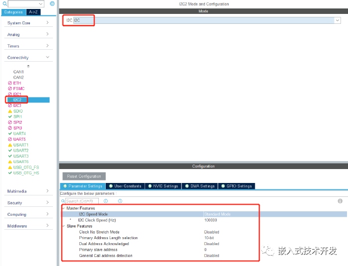
Using STM32CubeMX for configuration is very convenient. Basic configurations such as clock settings will not be detailed here, just look at the I2C configuration below:

The speed mode here is set to standard mode, with a clock speed of 100K. If higher performance is required, Fast mode with a 400K clock can be selected.
After configuration, generate the code.
Once the code is generated, you can directly call the functions to read and write data:
HAL_I2C_Mem_Read
HAL_I2C_Mem_Write
Function parameters can refer to the code comments.
When writing to the 24CXX series EEPROM, it is important to note that when writing across pages, there should be a certain delay; otherwise, the write operation may fail. The page size differs for different capacities.
Additionally, the addresses for capacities below 24C16 are 8 bits, while those for capacities above 24C32 are 16 bits. When calling read and write functions, be sure to select I2C_MEMADD_SIZE_8BIT or I2C_MEMADD_SIZE_16BIT accordingly.
In this test, a 24C64 is used, so I selected I2C_MEMADD_SIZE_16BIT.
To facilitate operations, I wrapped the read and write functions in another layer to account for various scenarios of cross-page writing, allowing for continuous writing at any address. The program is as follows:
#include "at24c64.h"
#include "i2c.h"
#define AT24CXX_ADDR_READ   0xA1
#define AT24CXX_ADDR_WRITE   0xA0
#define PAGE_SIZE   32

/**
 * @brief        Read multiple bytes of data from any address of AT24C64
 * @param        addr —— Address to read data (0-65535)
 * @param        dat  —— Address to store read data
 * @retval        Success —— HAL_OK
 */
uint8_t At24cxx_Read_Amount_Byte(uint16_t addr, uint8_t* recv_buf, uint16_t size){
    return HAL_I2C_Mem_Read(&hi2c2, AT24CXX_ADDR_READ, addr, I2C_MEMADD_SIZE_16BIT, recv_buf, size, 0xFFFFFFFF);
}

/**
 * @brief        Write multiple bytes of data to any address of AT24C64
 * @param        addr —— Address to write data (0-65535)
 * @param        dat  —— Address to store written data
 * @retval        Success —— HAL_OK
 */
uint8_t At24cxx_Write_Amount_Byte(uint16_t addr, uint8_t* dat, uint16_t size){
    uint8_t i = 0;
    uint16_t cnt = 0;

    // Count of bytes written
    /* For the starting address, there are two cases to consider */
    if(0 == addr % PAGE_SIZE )    {
        /* The starting address is exactly the page start address */
        /* For the number of bytes to be written, there are two cases to consider */
        if(size <= PAGE_SIZE)        {
            // If the number of bytes to be written does not exceed one page, write directly
            return HAL_I2C_Mem_Write(&hi2c2, AT24CXX_ADDR_WRITE, addr, I2C_MEMADD_SIZE_16BIT, dat, size, 0xFFFFFFFF);
        }
        else        {
            // If the number of bytes to be written exceeds one page, write the whole page in a loop
            for(i = 0;i < size/PAGE_SIZE; i++)            {
                HAL_I2C_Mem_Write(&hi2c2, AT24CXX_ADDR_WRITE, addr, I2C_MEMADD_SIZE_16BIT, &dat[cnt], PAGE_SIZE, 0xFFFFFFFF);
                HAL_Delay(3);
                addr += PAGE_SIZE;
                cnt += PAGE_SIZE;
            }
            // Write the remaining bytes
            return HAL_I2C_Mem_Write(&hi2c2, AT24CXX_ADDR_WRITE, addr, I2C_MEMADD_SIZE_16BIT, &dat[cnt], size - cnt, 0xFFFFFFFF);
        }
    }
    else    {
        /* The starting address deviates from the page start address */
        /* For the number of bytes to be written, there are two cases to consider */
        if(size <= (PAGE_SIZE - addr%PAGE_SIZE))        {
            /* Can finish writing within this page */
            return HAL_I2C_Mem_Write(&hi2c2, AT24CXX_ADDR_WRITE, addr, I2C_MEMADD_SIZE_16BIT, dat, size, 0xFFFFFFFF);
        }
        else        {
            /* This page cannot be finished writing */
            // First, finish writing this page
            cnt += PAGE_SIZE - addr%PAGE_SIZE;
            HAL_I2C_Mem_Write(&hi2c2, AT24CXX_ADDR_WRITE, addr, I2C_MEMADD_SIZE_16BIT, dat, cnt, 0xFFFFFFFF);
            addr += cnt;
            HAL_Delay(3);
            // Write whole page data in a loop
            for(i = 0;i < (size - cnt)/PAGE_SIZE; i++)            {
                HAL_I2C_Mem_Write(&hi2c2, AT24CXX_ADDR_WRITE, addr, I2C_MEMADD_SIZE_16BIT, &dat[cnt], PAGE_SIZE, 0xFFFFFFFF);
                HAL_Delay(3);
                addr += PAGE_SIZE;
                cnt += PAGE_SIZE;
            }
            // Write the remaining bytes
            return HAL_I2C_Mem_Write(&hi2c2, AT24CXX_ADDR_WRITE, addr, I2C_MEMADD_SIZE_16BIT, &dat[cnt], size - cnt, 0xFFFFFFFF);
        }
    }
} After testing, the hardware I2C read and write operations with the EEPROM function normally. No so-called bugs were found; of course, this is just a test of one EEPROM device with an M4 core, and further verification is needed for other cores (such as M3) and other I2C devices.
Using hardware I2C is relatively simple, as there is no need to adjust the timing manually, but it can only use a fixed number of pins.
Software simulated I2C can use any pins and is relatively easy to port for different MCUs, but timing adjustments can be troublesome for MCUs with different frequencies.
Both have their pros and cons, and the choice should be based on actual needs.