1. Resources
1.1 What Resources Are Available and How to Download Them
“Article 1: New Learning Path, Video Introduction, Resource Download”
“Chapter 2: Resource Download Methods”
100ask Technical Forum: http://bbs.100ask.net/
100ask Official Wiki (Resource Download): http://wiki.100ask.org/
Online Classroom: https://www.100ask.net/index
1.2 Which Chapters to Study in This Development Board Manual
This manual can be viewed as needed; beginners can even skip this manual initially because “Article 2: Environment Setup, Basic Linux Operations, Tool Usage” already introduces how to set up the environment and test the first APP and the first driver program.
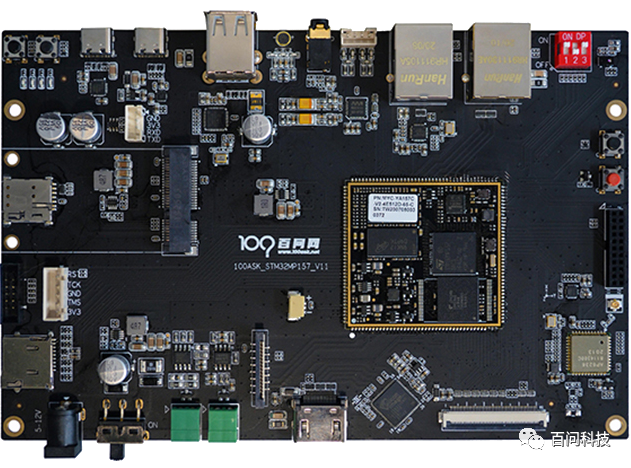
2. Introduction to 100ask_stm32mp157 Development Board
2.1 Overview of 100ask_stm32mp157 Fully Functional Development Board Hardware Resources
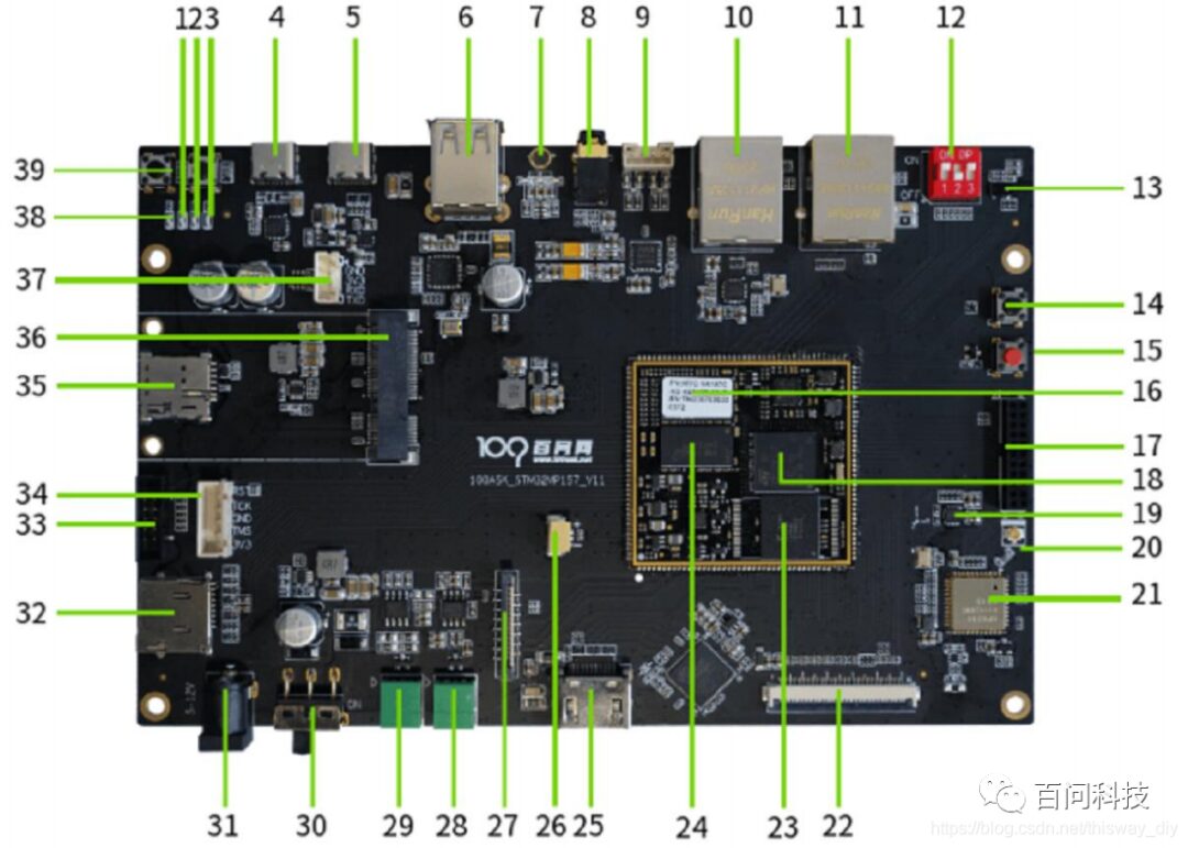
The meanings of the hardware labeled in the above development board image are as follows:
| 1. 4G Status Indicator | 21. AP6236 WIFI Bluetooth Chip |
| 2. LED User Light | 22. RGB888 Interface |
| 3. LED User Light | 23. eMMC |
|
4. TYPE C Serial |
24. DDR3 |
| 5. TYPE C USB OTG | 25. Standard HDMI Output Interface |
| 6. USB HOST*2 | 26. RTC Clock Interface |
| 7. Microphone Chip | 27. DSI Screen Interface |
| 8. 3.5mm Headphone Interface | 28. CAN Communication Interface |
| 9. LINE Audio Interface*1 | 29. RS485 Communication Interface |
| 10. USB Network Card Interface*1 | 30. Power Toggle Switch |
| 11. Ethernet | 31. 5.5mm DC Interface |
| 12. Boot Mode Toggle Switch | 32. micro SD Card Interface |
| 13. AP6216 Sensor Module | 33. JTAG/SWD Interface |
| 14. Wakeup Sleep Key | 34. SWD Interface |
| 15. Reset Button (Red) | 35. Nano SIM Card Slot |
| 16. DDR3 | 36. 4G Module Interface |
| 17. GPIO Expansion Pins | 37. TTL Serial Module Interface |
| 18. CPU | 38. Power Indicator (Red) |
| 19. ICM8235 Sensor Module | 39. User Button (Black)*2 |
| 20. AP6236 Chip Antenna Socket |
2.2 Overview of 100ask_stm32mp157 Fully Functional Development Board Software Resources
2.2.1 Development Environment
We provide basic VMware system image files for Ubuntu 16.04 LTS and Ubuntu 18.04 LTS versions made with osboxes. Based on this, we set up ordinary users and install essential software packages to ensure the image is minimal while allowing the system to be quickly used without excessive configuration. We also provide a one-click configuration environment script to help different users quickly solve environment configuration differences.
2.2.2 System Resource Introduction
All our source codes are managed uniformly using git + repo. Users can easily obtain the latest source code, view our commit history, and submit Pull requests or issues to continuously improve.
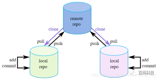
Tfa Version V2.2 Bootloader Version uboot 2020.02 Linux Kernel Version LinuxKernel 5.4 LTS
2.2.3 File System Introduction
Note: When we create the factory system, we used both Yocto and Buildroot. Beginners should not create the file system by themselves because:
① Yocto is Extremely Difficult to Use
The download program size alone reaches 10G, and it takes over 20 hours to compile on a regular personal computer. If you make slight modifications to the program, it takes at least half an hour to recreate it.
We had no choice but to use Yocto: QT GUI programs require some libraries that use the GPU, which we haven’t resolved on Buildroot yet.
-
Yocto uses the latest Yocto for the long-term support branch, based on which we add our own meta-layer data to support three customized distribution systems: using eglfs of qt5.14, using xwindows display of weston, and the minimal core system, which contains various common toolkits to help you quickly verify functionality.
-
Buildroot is based on Buildroot 2020.02 LTS, adapted for the 100ask_stm32mp157 development board, adding busybox systemV systemD system service support, making the system boot faster, the system image smaller, and including various commonly used software packages and tools.
Chapter 3: Booting the Development Board
3.1 Boot Mode Selection
The red toggle switch on the board is used to set the boot mode, supporting four modes: EMMC boot, SD card boot, USB flashing, and M4 (debug) mode.
A table is drawn on the back of the board indicating how to set these four modes. In the table, BOOT0 corresponds to switch 1, BOOT1 corresponds to switch 2, and BOOT2 corresponds to switch 3, as follows:
BOOT CFG
| BOOT | BOOT0 | BOOT1 | BOOT2 |
| EMMC | OFF | ON | OFF |
| SD | ON | OFF | ON |
| USB | OFF | OFF | OFF |
| M4(debug) | OFF | OFF | ON |
The setting diagram for these four boot modes is as follows:

The factory board has the system flashed on EMMC, and you can set it to EMMC boot mode.
3.2 Serial Connection
In the following operations, communication with the board is done via serial port. The serial port is short for serial interface, which means data is transmitted one bit at a time in sequence, characterized by a simple communication line.
3.2.1 Connecting Serial Cable and Power Cable, Configuring Serial Tool
As shown in the figure below, connect the serial cable to the computer and the board, and plug in the power supply for the development board.
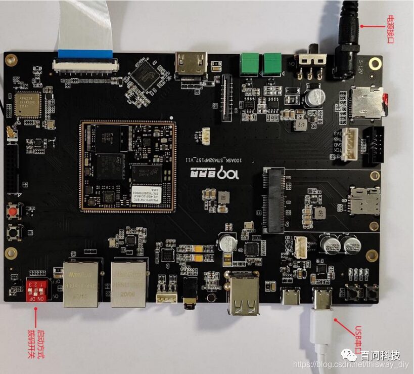
Particularly note the following points: ① Set the board’s boot selection to the correct boot mode, ensuring the selected mode has a system that can run; ② Ensure the board is plugged into the corresponding power supply as shown in the diagram; the power switch does not need to be turned on temporarily.
3.2.2 Installing USB Serial Module Driver
After connecting the Type C USB data cable, Windows will automatically install the driver (installation may be slow, wait about a minute). Open the computer’s “Device Manager” and under the “Ports (COM & LPT)” section, you can see the “(COM21)” as shown in the figure below. The “COM21” here may be different from what is displayed on your computer; remember the number displayed on your computer.
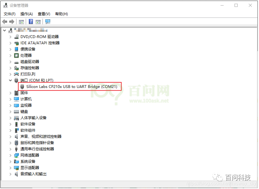
If the computer does not display the port number, you need to manually install the driver by downloading a driver wizard from the official website (www.drivergenius.com), installing, running, and detecting, which will automatically install the serial port driver.
3.2.3 Using MobaXterm Software to Open Serial Port
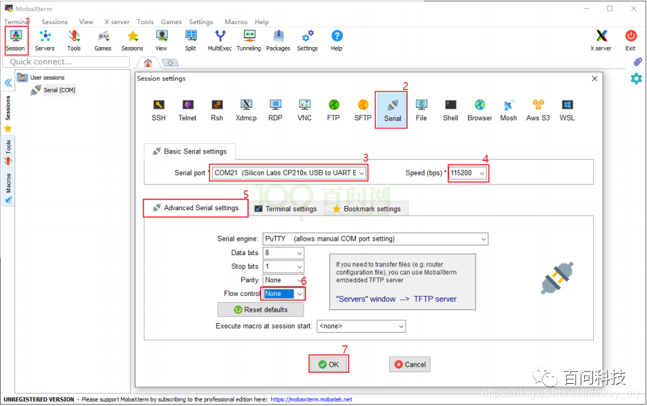
Open MobaXterm, click on the “Session” in the upper left corner, select “Serial” in the pop-up interface, as shown in the figure below, select the port number (the port number shown in the device manager COM21), baud rate (Speed 115200), flow control (Flow Control: none), and finally click “OK”. The steps are shown in the figure below.
Note: The flow control (Flow Control) must be set to none; otherwise, you will not be able to input data to the serial port in MobaXterm.
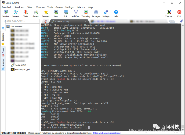
A window will then appear, and at this point, turn on the power switch of the board, and you will receive the data sent from the board’s serial port, as shown in the figure below.
3.2.4 The Development Board Login Name is root, No Password Required
When you see “100ask login:” in the serial port, enter “root” and press Enter, as shown in the figure below:

