The clamp multimeter is composed of a current transformer and a meter. The core of the current transformer can open when the clamp is tightened; the wire carrying the current to be measured can pass through the gap of the opened core without being cut, and when the clamp is released, the core closes.
The clamp multimeter is composed of a current transformer and a meter. The core of the current transformer can open when the clamp is tightened; the wire carrying the current to be measured can pass through the gap of the opened core without being cut, and when the clamp is released, the core closes.
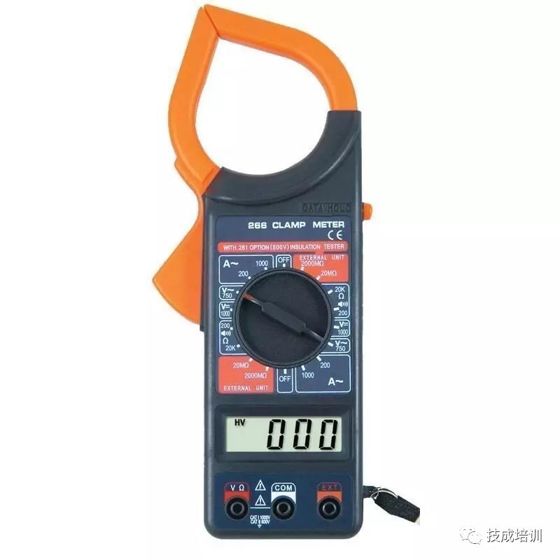
When we need to measure current without breaking the circuit, we need to use a clamp multimeter (sometimes abbreviated as clamp meter). A clamp multimeter is an instrument used to measure the amount of current in an electrical circuit that is in operation, and it is a commonly used measuring tool for electricians. Clamp multimeters are divided into two main categories: clamp AC current meters and clamp AC/DC meters, some of which can also measure AC voltage.
Structure:
The clamp AC current meter is essentially composed of a current transformer and a rectifying instrument. The wire carrying the current being measured acts as the primary winding of the current transformer, while the secondary winding of the current transformer is located on the core, connected to the rectifying instrument. Based on the certain proportional relationship between the primary and secondary windings of the current transformer, the rectifying instrument can display the current value of the measured circuit.
The clamp AC/DC meter is an electromagnetic instrument, where the wire being measured, placed in the clamp, acts as the excitation coil. The magnetic flux forms a loop in the core, and the electromagnetic measuring mechanism is located in the gap of the core, deflecting under the influence of the magnetic field to obtain the reading. Since its deflection is not affected by the measured current, it can measure both AC and DC currents.
Usage Method:
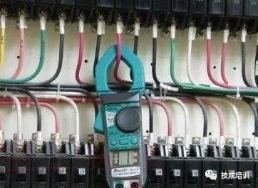
The usage method of the clamp multimeter is simple. As shown in the figure above, when measuring current, you only need to clamp the wire that is currently running into the jaws of the clamp multimeter, and then read the value on the digital display or dial.
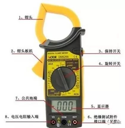
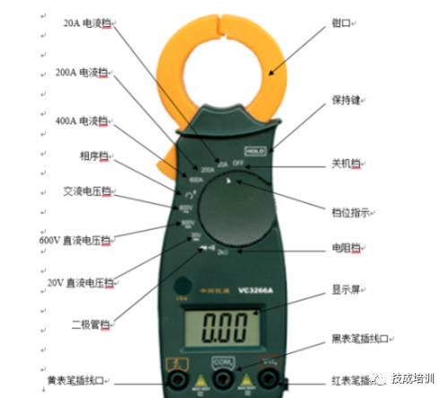
It’s pretty simple, right? Just clamp the measuring wire! However, the widespread use of digital clamp multimeters has added many multimeter functions, such as voltage, temperature, resistance, etc. (sometimes this type of multifunction clamp meter is called a clamp multimeter, as shown in the figure above, the instrument has two probe jacks); different functions can be selected through a knob, and the usage method is not much different from a general digital multimeter. For some specific function buttons, you should refer to the corresponding manual.
Phase Sequence Testing:
(1) Turn the dial to the phase sequence detection setting;
(2) Insert the probes yellow, black, red into the c, COMb, VΩa jacks respectively;
(3) Connect the red, black, and yellow probes to A, B, C (or L1, L2, L3). When the red and black probes are connected, the indicator light glows slightly; when the yellow probe is connected, the indicator light turns on, indicating positive phase sequence; if the indicator light goes out, it indicates reverse phase sequence;
(4) The phase sequence setting can also measure phase-to-phase voltage.
AC Voltage Measurement:
(1) Turn the dial to the AC voltage setting;
(2) Insert the red and black probes into VΩa, COMb jacks respectively;
(3) Connect the other end of the red and black probes to the measurement point and read the value.
AC Current Measurement:
(1) Select the appropriate current range;
(2) Fully clamp the wire to be measured with the jaws and read the data;
Note: The maximum test current for this instrument is only 600A, do not test currents exceeding 600A.
DC Voltage Measurement:
(1) Select the appropriate DC voltage range;
(2) Insert the red and black probes into VΩa, COMb jacks respectively;
(3) Connect the other end of the red and black probes to the measurement point and read the value.
Resistance Measurement:
(1) Turn the dial to the resistance range 2kΩ;
(2) Insert the red and black probes into VΩa, COMb jacks respectively;
(3) Connect the other end of the red and black probes to the measurement point and read the value;
Note: Resistance can only be tested when the power is off.
Circuit Continuity Measurement:
(1) Turn the dial to the diode setting;
(2) Insert the red and black probes into VΩa, COMb jacks respectively;
(3) Connect the other end of the red and black probes to the measurement point and read the value. If the value is very small and the multimeter emits a “beep” sound, the circuit is continuous; conversely, if the value displays “1” and the multimeter does not sound, the circuit is open or has a very high resistance.
Note: Circuit continuity can only be tested when the power is off.
(1) Before using a digital multimeter, carefully read the user manual to familiarize yourself with the functions of the power switch, range switch, input jacks, probe jacks, and various function keys, knobs, and accessories. Additionally, understand the multimeter’s limit parameters, recognize the characteristics of overload displays, polarity displays, low voltage displays, and other indicator displays and alarms, and master the rules for decimal point positioning. Before measuring, carefully check the probes for cracks, the insulation of the leads for damage, and whether the probes are correctly inserted to ensure the safety of the operator.
(2) Before each measurement, reconfirm the measurement item and range switch position, and whether the input jacks (or dedicated jacks) are correctly selected.
(3) When measuring, the instrument may show jumping values; wait for the display to stabilize before reading.
(4) Although digital multimeters have relatively complete protection circuits, attempts should still be made to avoid operational errors, such as measuring voltage with the current range, measuring voltage or current with the resistance range, or measuring charged capacitors with the capacitance range, to prevent damage to the instrument.
(5) If only the highest position shows the digit “1” and all other positions are off, it indicates that the instrument has overloaded; a higher range should be selected.
(6) Do not switch the range switch while measuring voltages above 10OV or currents above 0.5A to avoid arcing and burning the contacts of the switch.
(7) The numbers next to the dangerous markings on the input jacks represent the maximum input voltage or current limits. Exceeding these limits may damage the instrument and even endanger the operator’s safety.
(8) Clamp multimeters should not be used to measure current in high voltage lines; the voltage of the measured line should not exceed the voltage level specified by the clamp meter (generally not exceeding 500 volts) to prevent insulation breakdown and electric shock.
(9) Estimate the size of the current to be measured and select the appropriate range; do not use a small range to measure large currents.
(10) Before measuring, ensure that the range switch is set to the appropriate AC current range; do not use the voltage or resistance ranges to measure current.
Remember! Never use the resistance range or current range to measure voltage; if done accidentally, the meter may be damaged.
(11) Each measurement should only clamp one wire. When measuring, the wire to be measured should be placed in the center of the jaws to improve measurement accuracy. It is best to hold the meter level with your hand, without allowing the wire to touch the jaws and meter body.
(12) After measurement, the range switch must be turned to the maximum voltage range position before turning off the power switch to ensure safe use next time.
Complete Question Bank for Electrician’s Primary Exam 2021 (includes answers)
Is troubleshooting frequency converters difficult? Just one click!
Can you brush through all electrical exam questions with one click? Don’t you have this amazing tool yet?
Which of the five major electrical drawing software (CAD, Eplan, CADe_simu…) do you choose?
The latest electrical CAD drawing software, with a super detailed installation tutorial!
The latest electrical drawing software EPLAN, with a super detailed installation tutorial!
Common issues for beginners using S7-200 SMART programming software (with download link)
Comprehensive electrical calculation EXCEL sheet, automatically generated! No need to ask for electrical calculations!
Bluetooth headphones, electrician/PLC introductory books available? Come and get your electrical gifts!
Basic skills for PLC programming: Ladder diagrams and control circuits (with 1164 practical cases of Mitsubishi PLC)
Can’t understand electrical diagrams yet? Get the basics of electrical diagram reading and simulation software to quickly get started with theory and practice!
12 free electrician videos, 10GB software/eBook materials, and 30 days of free electrician live classes are available!