1. What is BOOT?
Most beginners are often puzzled by the term BOOT when they first encounter it. Where did this strange thing come from that requires jumper caps? Why do we need to configure it to download programs via serial port? What happens if it is not configured correctly, leading to the microcontroller failing to start properly…
Boot, a transitive verb, refers to “starting a computer by loading the operating system into memory,” originating from bootstrap (verb), which comes from bootstrap (noun), meaning “a fixed sequence of instructions for loading a computer operating system” (1953). So why is bootstrap referred to as “a fixed sequence of instructions for loading a computer operating system”?
Boot-strap originally referred to a small loop or ring at the top back of a man’s boot, which the wearer could hook with their fingers to pull the boot on. By 1871, in the last “practical problem” of the first chapter of Steel’s “Popular Physics,” there was a question: “30. Why can’t a person lift themselves by pulling on their bootstraps?” Hence, it was later used metaphorically for an impossible task and also to suggest “improving oneself through strict, independent effort.” This perfectly aligns with the function of a computer system’s boot loader — the first program loaded pulls itself up via bootstrap. The computer system lifts itself by pulling on its own bootstraps through BOOT.
In STM32, BOOT is short for Bootloader. The bootloader is a special piece of code located inside the chip that is responsible for executing some initialization operations during the microcontroller’s startup process and loading user applications or firmware.

2. STM32’s BOOT
STM32’s BOOT is controlled by the high or low levels of the BOOT0 and BOOT1 pins.
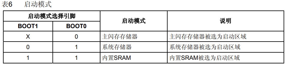
How do BOOT0 and BOOT1 control BOOT?
After a system reset, the value of the BOOT pins will be latched on the fourth rising edge of SYSCLK. Users can set the states of the BOOT1 and BOOT0 pins to choose the startup mode after reset.
When exiting from standby mode, the value of the BOOT pins will be latched again; therefore, the BOOT pins should remain in the required startup configuration during standby. After a startup delay, the CPU fetches the stack top address from address 0x0000 0000 and starts executing code from the address indicated by the startup memory at 0x0000 0004.
Starting from Flash: This is the most commonly used startup method. In this mode, the reset vector and application code are stored in the main Flash memory. When the microcontroller resets, the CPU starts executing code from the starting address of Flash (usually 0x0800 0000). Flash memory is typically used to store firmware, applications, and other common data.
Features and Uses:
Suitable for most application scenarios, especially those requiring long-term operation.
Provides a large storage capacity, capable of accommodating larger code and data.
Code and data can be programmed into the Flash memory during development using a programmer.
Starting from System Memory: Some models of STM32 microcontrollers have built-in system memory, which is usually a small segment of Flash memory. In this mode, the reset vector and application code are stored in the system memory. When the microcontroller resets, the CPU starts executing code from the starting address of the system memory (usually 0x1FFF 0000).
Startup address: 0x1FFF0000 starts from system memory, which is a specific area inside the chip, pre-loaded by ST (STMicroelectronics) with a Bootloader at the factory, also known as an ISP (In-System Programming) program. This Bootloader is a read-only memory (ROM) that cannot be modified after factory settings.
When BOOT0 is set to 1, BOOT1 is set to 0, and the reset button is pressed, the microcontroller starts executing from the Bootloader in the system memory. This Bootloader has the capability of downloading programs via serial port, allowing programs to be downloaded to the microcontroller’s Flash memory through the serial port.
When using this startup mode, the following steps are typically required:
Set BOOT0 to 1, BOOT1 to 0, and press the reset button to start the microcontroller from the system memory Bootloader.
With the help of the Bootloader, download the program to the Flash memory via the serial port.
After the program download is complete, set BOOT0 to GND (ground), manually reset the microcontroller to start from the Flash memory.
Indeed, downloading programs via the serial port is relatively cumbersome, requiring pin configuration and manual operation, which is not very convenient. Therefore, this startup method is not commonly used in practical applications unless specific needs require program downloading via serial port. Generally, starting from Flash is a more common and convenient method.
Features and Uses:
System memory is typically used to store special-purpose startup code, bootloaders, or bootloaders, etc.
Can be used to update firmware, programs, or configuration parameters at runtime via external interfaces (such as serial ports, USB, etc.).
Provides an alternative startup method for recovery in case of Flash memory issues or when erasing is needed.
Built-in SRAM Startup: STM32 microcontrollers also provide an option to start from built-in static random-access memory (SRAM). In this mode, the reset vector and application code are stored in SRAM. When the microcontroller resets, the CPU starts executing code from the starting address of SRAM (usually 0x2000 0000). Built-in SRAM startup is usually used for program debugging and rapid prototyping development. In this startup mode, the reset vector and program code are stored in the built-in static random-access memory (SRAM).
Built-in SRAM is a high-speed temporary memory, unlike Flash memory, it has read and write capabilities. Therefore, running code in SRAM allows for quick program debugging and modification.
When the startup address is set to the starting address of SRAM (usually 0x2000 0000), the microcontroller starts executing code from the reset vector in SRAM. This way, you can modify and debug code in SRAM without needing to erase the entire Flash memory. By starting from built-in SRAM, the efficiency of program debugging can be improved, avoiding the time consumption of erasing the entire Flash memory with each modification. However, it should be noted that the capacity of built-in SRAM is relatively small and cannot accommodate large programs. Therefore, this method is more suitable for rapid code debugging and small-scale program development. For formal production and deployment, the code still needs to be downloaded to Flash memory for long-term operation and stability.
Features and Uses:
Allows loading and executing code at runtime without reprogramming the Flash memory.
Suitable for applications that require dynamic updates of firmware, programs, or configurations at runtime.
STM32 Startup Address
In the ARM Cortex-M3 processor, it is specified that execution starts from address 0 after power-up. However, STM32 stores the interrupt vector table at address 0x0800 0000 in Flash memory. To maintain consistency with the ARM Cortex-M3 specification, STM32 adopts a startup mapping method.
This startup mapping is controlled by the states of the BOOT0 and BOOT1 pins. When the main Flash startup mode is selected, i.e., when the BOOT0 pin is low and the BOOT1 pin is at any level, the chip will perform a startup mapping process after power-up. During this process, the address 0x0800 0000 in Flash memory is mapped to address 0 in memory.
When the interrupt vector table is stored at address 0x0800 0000 in Flash memory, regardless of whether the ARM Cortex-M3 core reads instructions from address 0 or 0x0800 0000, it can correctly access the interrupt vector table. This is because, during the startup mapping process, address 0x0800 0000 is mapped to address 0, which does not affect the core’s reading. It is important to note that the code is still stored at address 0x0800 0000 in Flash memory; it is just that address mapping is performed during the startup process. This allows the ARM Cortex-M3 startup rules to be maintained while placing the interrupt vector table at a fixed address in Flash memory for easy access and management.
Circuit Analysis

The main structure of the circuit consists of a 3*2 pin header. Most importantly, the two current-limiting resistors R3 and R4 play a crucial role in limiting the current. This is very important because many students’ boards have been damaged due to forgetting these two current-limiting resistors.