
Introduction
Uh, why am I writing this tutorial~I don’t know either!Ah, too much to say brings tears, it’s hard, so competitive~
The following content is my personal understanding, and there may be errors in the explanations of technical terms, so I hope the readers will point them out, thank you very much!

Basic Concepts
Returning to the content, today I will use this blog post to guide everyone in exploring Arduino, getting started with digital and analog electronics, and entering sensor-driven design!
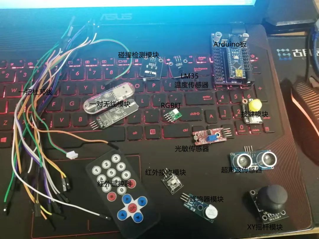
These are the items I’ve prepared: a set of DuPont wires, some sensors, and a board!
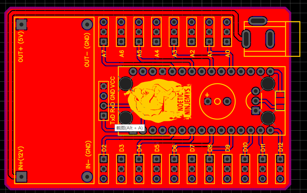
DuPont wires are used to connect the sensor modules to the microcontroller (Arduino board). The Arduino board here is the one I used in the dual-arm robotic arm course, which is actually an expansion board for the Arduino Nano, bringing out all the IO ports (except for pin D13). Pin D13 is connected to a buzzer, and there is an LM2596S-5.0 module that implements a 12V to 5V 3A (maximum 3A output) voltage regulation function.
When playing with microcontrollers, what everyone is dealing with are the IO ports, which are the pins! These pins have two forms: input (Input) and output (Output), hence they are called IO ports.
In electronics, you often hear about digital and analog electronics, and the pins of the microcontroller are also divided into digital (digital) and analog (analog).
When playing with microcontrollers, the terms ADC and DAC are unavoidable!ADC, Analog Digital Change, converts analog to digital, analog quantity collection.
DAC, Digital Analog Change, converts digital to analog, digital quantity output.
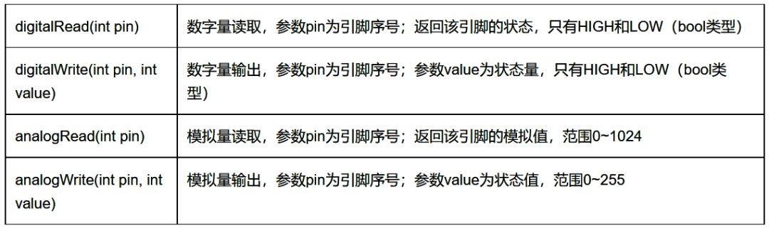
Therefore, Arduino programming has the following four functions:
So what are digital and analog? What is digital electronics, and what is analog electronics?
Let’s take a light bulb as an example. We control the light bulb’s on and off with a switch, where we define the light being on as 1 and off as 0. This way of thinking, which conforms to normal human logic, is called positive logic; there is also a definition where the light being on is 0 and off is 1, which is called negative logic. There is essentially no difference between positive and negative logic because we are used to the logic that something being present is 1 and absent is 0 (recommended reading “Programming Pearls”).
We divide signals into present and absent, or the current voltage value is HIGH or LOW, or the current state is 0 or 1. This is digital quantity—quantities that only have two states: 0 and 1. In our microcontroller, this corresponds to the IO pin outputting a high signal or a low signal, detecting whether that IO pin is high or low!
Now, what about analog quantity? Let’s still take the light bulb as an example. Digital quantity can indicate whether the light is on, but what about the brightness of the light? We can control whether it is on or off, but can we control the brightness? The answer is yes! The quantity used to represent a certain degree is the analog quantity! We can output an analog quantity through the microcontroller’s pin to control the “degree (brightness of the light, loudness of sound, etc.)”; this is DAC. Similarly, we can obtain the sensor’s “degree (temperature, humidity, voltage value)” through the microcontroller’s pin; this is ADC!
So, how is ADC collection and DAC output achieved? We are using the Arduino Nano, which has 8 ADC analog reading pins from A0 to A7. These pins can also be used as regular IO, in the order of A0 to A7 corresponding to 14 to 21. Among them, pins A4 and A5 are reused as IIC communication pins (if you don’t understand, it’s okay; we’ll learn this later).
The ADC collection precision of Arduino is 10 bits, so the values read range from 0 to 1024 (2^10). The ADC values here actually represent voltage values, and the reference voltage (Aref) for Arduino’s analog quantity is by default 5V. This means that during ADC collection, it reads the voltage value from 0 to 5V and converts it into a value from 0 to 1024 for output.
As for the DAC output of the Arduino Nano, it is achieved through PWM (Pulse Width Modulation technology), with PWM-capable pins being D3, D5, D6, D9, D10, and D11.
Speaking of PWM, let’s first discuss two concepts—frequency and duty cycle!
The term frequency should be familiar to everyone; it refers to the number of times periodic changes occur within a unit of time, which we generally default to one second.For example, if I execute 20 times in one second, I can say the frequency is 20Hz, where frequency = 1/unit time.
The concept of duty cycle might be less familiar. Let’s make an assumption: if a microcontroller’s pin outputs a frequency of 20Hz, how long does it take to produce a frequency of 1Hz? The answer is 1s/20=0.05s=50ms!
This means that I control the microcontroller’s pin to complete a high-low level change every 50ms, achieving 20 high-low level changes within 1 second, which is controlling the microcontroller’s pin to output a frequency of 20Hz.
If I keep the pin at a high level for 10ms and at a low level for 10ms within 20ms, the duty cycle is 50%; if I keep the pin at a high level for 5ms and at a low level for 15ms, the duty cycle is 25%. So, the duty cycle is the ratio of the time spent at a high level to the total period of the level change.
PWM produces a square wave signal (as well as sine waves, triangular waves, etc.; we will discuss these later), and the PWM precision of Arduino is 8 bits, so the output PWM values range from 0 to 255 (2^8). The default frequency is 490Hz (generally considered to be 500Hz). Here is a reference material:
https://www.cnblogs.com/lulipro/p/6092264.html
There are too many images, and I don’t want to draw; someone else has done a good job!
Digital input is when the pin reads signals from sensors, which can be either high or low, such as from a button module.
Digital output is when the pin outputs a high or low signal, for example, lighting up an LED with the microcontroller pin. Analog input is when the pin senses a voltage value and converts it into a numerical value, such as reading the temperature from a temperature sensor.
Analog output is when the pin outputs a voltage value. The analog output range of Arduino is 0 to 255, meaning the voltage value from 0 to 5V is divided into 255 parts. By adjusting the voltage value, we can control the output level of the pin (here, think of it as power).
These four are the basic concepts of microcontrollers. If you are a seasoned microcontroller player, you may have heard of the five terms: push-pull, open-drain, floating, pull-up, and pull-down! We will deal with these later.
As mentioned above, analog output is achieved through PWM, and PWM is realized by the rapid switching of high and low levels on the pin. So why can this control the output level of the pin? This question is left for everyone to ponder, and here’s a hint: analyze it in conjunction with the blinking of an LED. What happens if the blinking frequency of the LED increases? What happens if you adjust the duty cycle of the blinking frequency? Leave it for everyone to think about and try!
This concludes the supplement to basic concepts; next, we will start our practical content!

Practice
At the beginning of the article, I pasted a picture of the components I currently have. Next, I will use these components to demonstrate Arduino programming!
Recently, I took two courses at Guyue Academy—PCB design and CAD design, which should be online in a couple of days. They are open courses, free of charge, and each course lasts over an hour! The board I used is one I designed myself; now, Lichuang’s PCB manufacturing is free, which is quite convenient!
If you don’t have these items on hand, it’s okay; you can go to this website for simulation, and the effect is the same, just make sure your internet connection is good! Arduino Online Simulation:
https://www.tinkercad.com/
I am using the Arduino Nano development board + LM2596S-5.0 buck module, and I have left out all the pins of the Arduino Nano in the order of Sign Vcc Gnd to avoid running out of Vcc and Gnd pins.
At the same time, I used a DC 5.5-2.1 (outer diameter 5.5mm, inner diameter 2.1mm) socket, which is a common model. The LM2596S-5.0 achieves an output of 5~40V and a maximum output of 5V 3A, with the pins left in the order of SVG, allowing direct connection to servos, which means this board can be directly used for robotic arms! Here’s a link to my previous blog “Design of a Six-Axis Robotic Arm Based on the Firmata Protocol and ROS Moveit”:
https://www.guyuehome.com/bubble/detail/id/39
The board is different, but everything else is the same! If you don’t understand the blog post, you can buy my courses at Guyue Academy, “Soft and Hard Combination to Play with ROS Robotic Arms” or “MoveIt to Control Dual-Arm Robots”; either one is a good start! The board looks like this!
Oh right, I didn’t bring out pin D13. This pin has an LED connected on all Arduino boards, which changes levels during program upload or power on/off. Here I connected pin D13 to the buzzer, so the buzzer will sound during program upload or power on/off, serving as an alert!
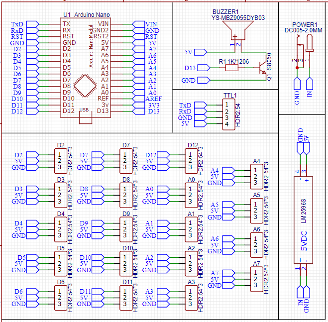
The schematic is very simple, just leave the pins out! For the buzzer, I used a transistor to control it. When the base is at a high level, the transistor conducts, allowing 5V through the transistor and the buzzer to flow to GND, causing the buzzer to sound; when the base is at a low level, the transistor is in cutoff state, creating a short circuit, preventing current from flowing and the buzzer from sounding!
Nothing else is complicated; it’s quite simple! As for cost, the Arduino Nano is under 20 yuan, and the LM2596S-5.0 is under 5 yuan, so you can get everything done for under 30 yuan; for sensors and DuPont wires, you can borrow from the school lab!

Code
Having discussed the hardware, let’s talk about the software code! As for the Arduino environment and how to download the program, you can just Google it; it’s really a pain to write that! If you don’t mind, I plan to create a public course on this part in a few days!
For the basics of Arduino syntax, here’s a link for your reference! Arduino Syntax Tutorial:
https://www.ncnynl.com/category/arduino-language/
The syntax of Arduino includes both C and C++; I mostly use C because writing simple functions in an object-oriented way isn’t very interesting; practicality is the way to go! Of course, if you are working on libraries, I suggest you use C++, or else you might get criticized (personal opinion; I can write terrible code, but you can’t. Because I can Ctrl C + Ctrl V your code).
Let’s first look at an example Arduino program—blinking an LED, with the code as follows.
//Define the pin where the LED is located#define LED 13 //Initialization function, the program starts here, the content of the setup function is executed only oncevoid setup(){ pinMode(LED,OUTPUT); //Set the LED pin to output mode digitalWrite(LED,LOW); //Set the LED pin to low level} //After the setup function is executed, the content of the loop function is executed in a loopvoid loop(){ digitalWrite(LED,HIGH); //Set the LED pin to high level delay(1000); //Delay 1000ms digitalWrite(LED,LOW); //Set the LED pin to low level delay(10000); //Delay 1000ms}Here, two new functions have been added—pinMode and delay.
pinMode sets the pin mode, and we need to specify the mode of the pin before using it (analog input does not need to be specified because it is predetermined).
pinMode(uint_8 pin,uint_8 mode) //Parameter pin is the pin number, mode is the mode, with OUTPUT and INPUT as the two valuesdelay(unsigned long ms) //Parameter ms is the delay time, in msThe logic here, if converted to C language, would look like this; everyone can compare and understand!
void setup(){ //Execute initialization} void loop(){ //Execute the main function} int main(){ setup(); while(1) { loop(); } return 0;}Uh, that’s basically the idea!
Now that we have a rough introduction to Arduino, the next step is how to use these sensors, so stay tuned for my upcoming blogs!

Conclusion
The concepts above are not only applicable to Arduino; they are universal for all microcontrollers and embedded systems. When learning different microcontrollers, everyone can compare!

“Mastering Deep Learning and Autonomous Driving with MATLAB”• Tongji Zihai“:If you’re interested in autonomous driving, familiar with MATLAB, and understand the basics of deep learning, computer vision, lidar, and sensor fusion technology, it’s time to scan the QR code below to enroll!
(Scan the QR code for details)