This article is authorized by the WeChat public account Electronic Development Learning.
Reply with “Little Horse Quadrotor” in the backend to obtain relevant materials for the Little Horse Quadrotor.
RoboFly is a completely open-source quadrotor launched by the Little Horse team in August 2018. This article provides the complete set of materials for this quadrotor.
Below are screenshots of the overall block diagram, schematic, PCB, physical images, and source code of the RoboFly quadcopter. Let’s take a quick look first, and then I will introduce it in detail.
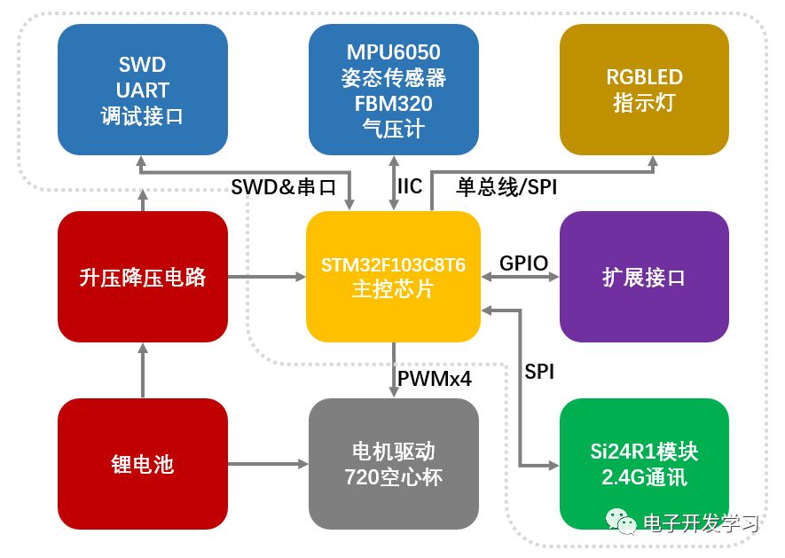
▲ Figure 1: Overall Block Diagram of RoboFly Quadrotor
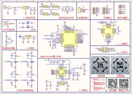
▲ Figure 2: Schematic of RoboFly Quadrotor
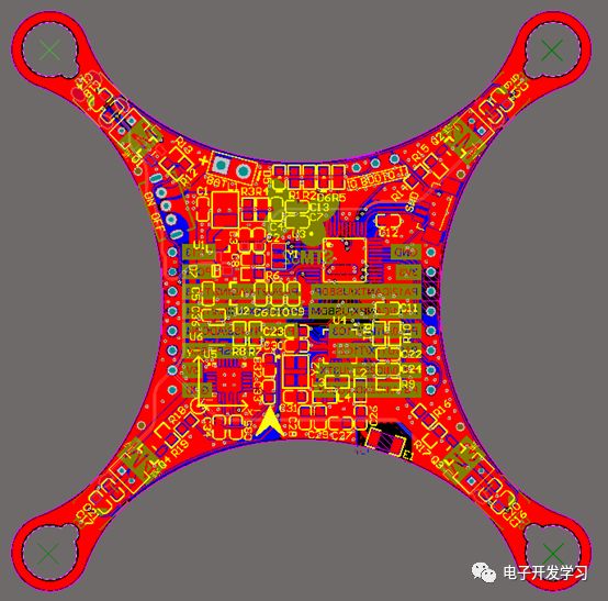
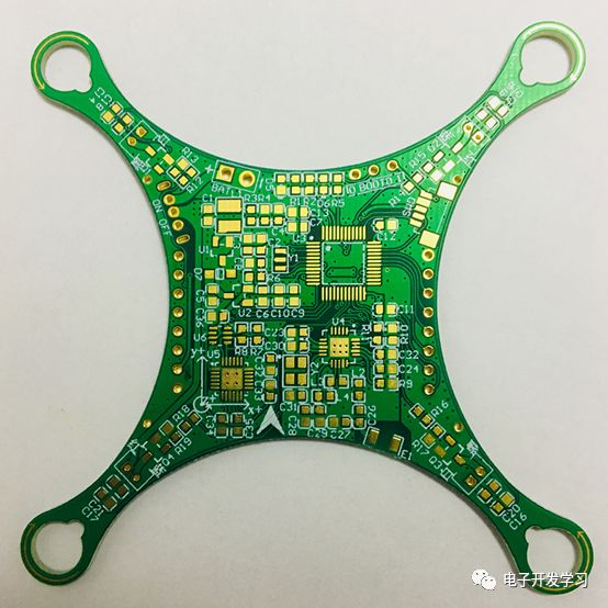
▲ Figure 3: PCB Diagram of RoboFly Quadrotor
▲ Figure 4: 3D Top View of RoboFly Quadrotor PCB
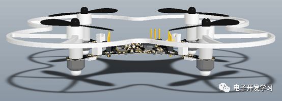
▲ Figure 5: 3D Front View of RoboFly Quadrotor PCB
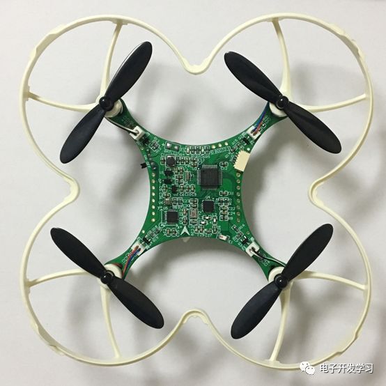
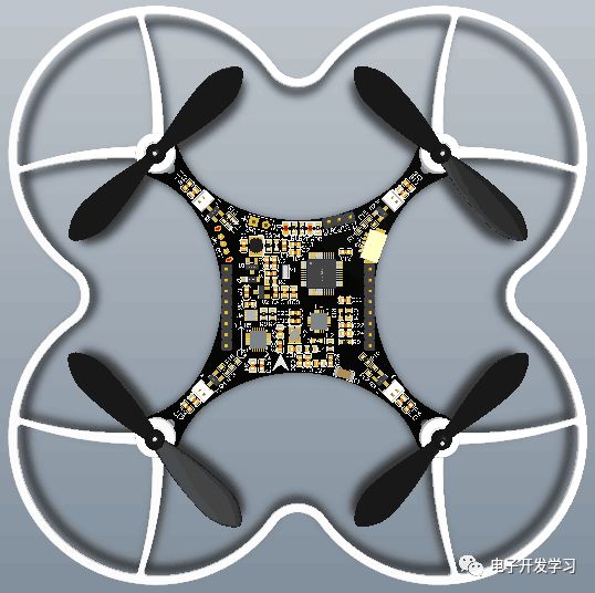
▲ Figure 6: Physical Image of RoboFly Quadrotor
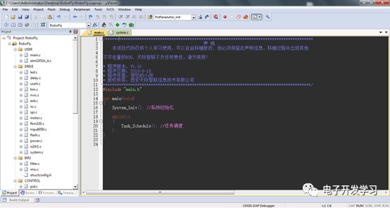
▲ Figure 7: Screenshot of RoboFly Quadrotor Source Code
The intention behind making and open-sourcing this quadrotor is as follows:
1. Beginners need a low-cost, complete hardware and software documentation, and technical support quadrotor learning platform;
2. Sold in component form, the circuit board layout and component packaging selection should facilitate soldering assembly;
3. The required components for the quadrotor should be easy and reliable to procure, ideally providing a one-stop shopping experience, to avoid excessive shipping costs, long procurement cycles, and the procurement of unqualified components that hinder learning progress.
4. The source code should be extremely concise, making it easy for beginners to learn and implement their own code;
5. Retain certain expansion interfaces, allowing users to easily expand functionalities such as altitude hold, trajectory tracking, and line following. After learning about quadcopters, this open-source quadrotor board can still be used as an STM32 development learning board;
Basic configuration of RoboFly quadrotor is as follows:
Main control chip: STM32F103C8T6
Attitude detection: MPU6050
Barometer: FBM320
Wireless chip: SI24R1
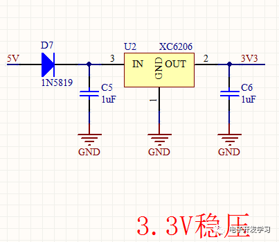
Power supply scheme: HT7750SA boost + XC6206 regulator
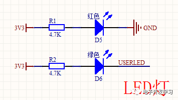
Indicator lights: 1 power indicator LED, 1 user programming LED, 4 single-bus full-color RGB lights
Battery: 600mAh 20C 1S lithium-ion battery
Motor: 720 hollow cup
Propeller: 55mm propeller
Propeller guard: adjacent axis distance 65mm
Frame: PCB integrated frame
Endurance time: 10 minutes
Remote control distance: 50m in open space
Simple explanation of each module in the RoboFly quadrotor schematic:
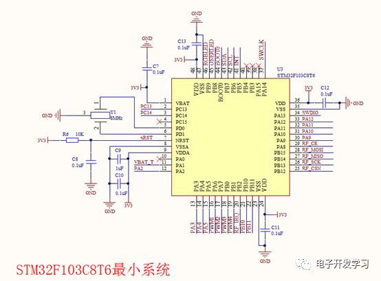
STM32F103C8T6 is an MCU released by ST in 2007. As of now, ST has released the STM32H7 with speeds up to 400MHz (at this point, some may mention the 600MHz thing, which I am also aware of). I have used STM32F1, STM32F4, and STM32F7 for various quadcopters, but for this open-source quadrotor, I chose the STM32F103C8T6 mainly for three reasons: first, the package is relatively large, making it easier for beginners to solder; second, it is low-cost, resulting in a lower learning cost; third, there is a wealth of information available online for beginners to learn and use.
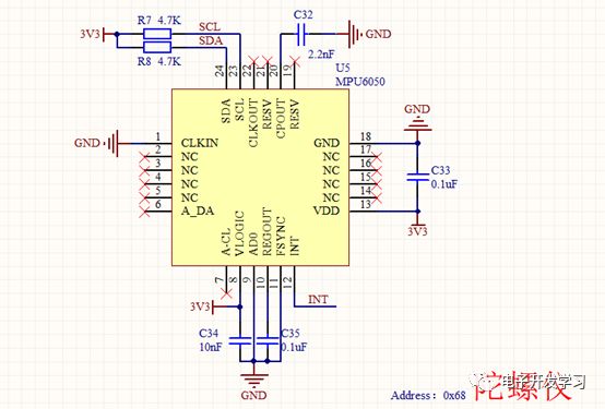
The attitude sensor selected is the MPU6050, mainly considering that it has a relatively large package, can be directly soldered with a soldering iron, and is also low-cost with abundant documentation. Moreover, it comes with a DMP library that can directly output attitude angles to the main control chip after attitude calculation. Our first quadcopter in 2016 used the DMP library to output attitude angles.
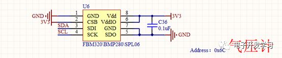
The barometer used is the FBM320, which I personally think has average performance. However, its advantage is that this package is compatible with BMP280 and SPL06 pin configurations, making it easy to replace. However, placing a barometer on a quadrotor can be troublesome because it requires finding a way to eliminate the interference from the propeller’s wind. Materials like sponge can be used for isolation.
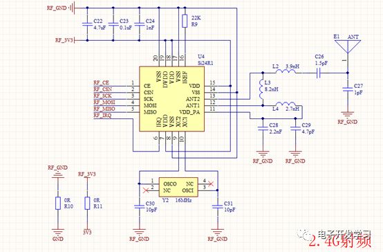
The wireless chip used is the SI24R1, a domestic product. The reason for using this instead of the NRF2401 is that, after testing, its performance is acceptable, and its pins are fully compatible with the NRF2401. The wireless transmission can achieve 7dB, and with ceramic antennas at both the transmitting and receiving ends, a communication distance of 50m can be achieved. Adding an AP should allow for a distance of 100 meters without issue. By using two low-cost zero-ohm resistors for single-point grounding of the power supply, we prevent current fluctuations in the motor circuit from interfering with the RF circuit.
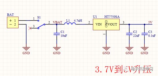
For the power supply scheme of boosting and then bucking, I discovered this when making my first quadcopter. When powering four hollow cup motors with a single-cell lithium-ion battery, if all four motors are loaded with propellers, the momentary acceleration to full speed can drop the battery output voltage below 3V. My tests showed it could even drop to 2.8V; if not boosted and directly powered the LDO, the LDO would fail. Therefore, powering the microcontroller system through boosting and then bucking is a feasible solution. Another option is to use a slow start when starting the motors, so the battery voltage does not drop suddenly, but this method limits the aggressiveness of the quadcopter and makes it less thrilling to fly.
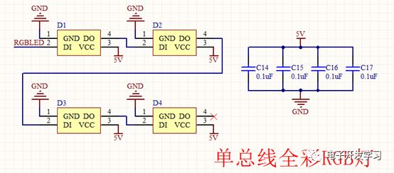
The RGB LEDs used on the four arms are serial single-bus full-color lights, meaning only one IO port of the microcontroller is required to control these four lights to emit various colors. These lights are similar to WS2811, achieving data communication through zero code to control the color of the lights. For beginners, understanding timing can often be difficult, and these lights can serve as the simplest example for learning timing; although simple, they are very interesting.
Due to the size and weight limitations of the quadcopter, the battery should ideally not exceed 600mAh; otherwise, the battery’s own weight will become the biggest burden. A battery that is too small cannot provide sufficient endurance. In summary, I believe that a capacity of 600mAh is a turning point. The battery should ideally come with a protection board for safety. Otherwise, swelling, failure is minor, but in severe cases, it could explode during flight.
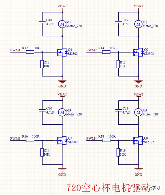
For the most critical component of this quadcopter—the hollow cup motors, it has been quite a journey. After two years of working with quadcopters, I spent a year searching for qualified hollow cup motors. In 2017, one quadcopter was affected by excessive lateral vibration from the motors, leading to significant lateral vibrations after the propellers turned, severely interfering with the accelerometer and causing large angular deviations, making it almost impossible to fly vertically. Initially, I suspected issues with the MOSFETs, gyroscope, and circuit design, but after performing FFT on the original data, I identified the interference frequency, confirming it was caused by the lateral vibrations of the motors. There were also instances where motors from the same batch displayed significant performance differences, leading to substantial variations in PID tuning outputs, ultimately affecting the lifespan of the MOSFETs and motors. The hollow cup motors are driven by the SI2302 MOSFET, which is a common, inexpensive, and effective MOSFET. However, there are many fakes on the market. There is much debate about whether to add capacitors or diodes in the motor drive circuit. My tests found that adding capacitors worked well, while adding diodes had a mediocre effect. This may also be due to insufficient rigor in the testing method, and we can discuss this issue further later.
When selecting propellers, it is essential to choose well-balanced ones; poorly made ones may affect balance, leading to lateral vibrations during flight.
It is common for beginners to crash or lose control while debugging quadcopters, so adding propeller guards can significantly reduce the likelihood of damaging the propellers and motors.
If using isolation between the flight control board and the frame, it can help reduce vibration effects to some extent, but this may increase weight and cost. Therefore, I chose a PCB frame, which is the easiest solution for beginners to implement, but not the only one. To facilitate soldering and debugging for beginners, I did not use black ink during board production but instead used green matte ink with a gold immersion process, making soldering and debugging easier.
The quadcopter source code uses Keil MDK V5.20;
The STM32 library used is the standard library;
The method for creating the quadcopter source code project can refer to our minimal system board course, with the course video available on the public account: Chapter 2, Lecture 2 of the STM32 Minimal System Board Tutorial | Project Template Setup.
Reply with “Little Horse Quadrotor” in the backend to obtain relevant materials for the Little Horse Quadrotor.
The link includes the following five files:
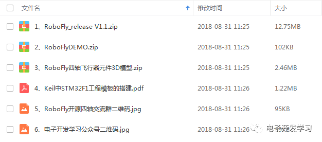
1. RoboFly_release V1.1.zip (PCB project created using AD09)
2. RoboFlyDEMO.zip (source code project created using Keil MDK V5.20)
3. RoboFly quadrotor component 3D model.zip(3D model created using Solidworks 2013)
4. Building STM32F1 project template in Keil.pdf
5. RoboFly open-source quadrotor group QR code.jpg
6. Electronic Development Learning public account QR code.jpg
The above is the description of the RoboFly quadrotor. We share open-source quadcopter materials without enticing sharing or setting conditions; everyone can directly copy the link into the browser to download. If you have different thoughts, feel free to leave comments below the public account for discussion. If you can conveniently click on the ads at the bottom of the article, it would be the greatest affirmation for us.
Regarding how to create beautiful 3D views of PCB components, in short, it is: “Create the model in 3D modeling software like Solidworks, save it in step format, then open the component library in AD, place the component body, set the parameters in the pop-up dialog, close the dialog, and press the number key 3 to switch to 3D view to see the created 3D effect.” If this statement is unclear, you can refer to how to create stunning 3D effects for PCB boards.
This article is authorized by the WeChat public account Electronic Development Learning.
Long press the QR code to follow us!