A quadcopter is a compact aircraft with a unique flight method, which has advantages such as simple structure, low failure rate, and the ability to generate greater lift per unit volume compared to ordinary aircraft. It has broad application prospects in both military and civilian fields. This article teaches you how to DIY a simple quadcopter.
This design mainly utilizes Inertial Measurement Unit (IMU) attitude acquisition technology, PID motor control algorithm, 2.4G wireless remote control communication technology, and high-speed hollow cup DC motor drive technology to achieve a simple quadcopter solution. The entire system design includes the flight control part and the remote control part. The flight control part adopts an integrated design of the frame and the control core to enhance system stability, while the remote control part uses analog joystick operation input for an excellent operating experience. Communication between the two parts is ensured by a 2.4G wireless module for stable data transmission. The flight control board uses the high-speed microcontroller STM32 as the processor and employs the MPU6050 motion sensor with a three-axis gyroscope and three-axis accelerometer as the inertial measurement unit. Communication is conducted via the 2.4G wireless module and the remote control board, ultimately driving the hollow cup motor through PWM based on the PID control algorithm to achieve remote control objectives.
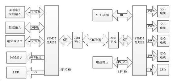
The hardware design of the system is mainly divided into two parts: the remote control board and the flight control board. The remote control board adopts a common game controller shape with a joystick for control input, and data transmission is done via a 2.4G wireless module. The flight control board integrates the control processing core and the frame design, meaning that the processor and motor are integrated on the same circuit board, using standard dimensions compatible with ordinary toy accessories. The software design of the system also includes the operation of both the remote control board and the flight control board. The software design of the remote control board mainly includes ADC acquisition and wireless data transmission. The software design of the flight control board mainly includes receiving wireless data, real-time calculation of its own attitude, calculation of motor PID increments, and driving the motors. The entire quadcopter system includes personnel operating the remote end and the aircraft control end. The main controller STM32 of the remote control end collects joystick data through the ADC peripheral and sends the collected data to the flight control end via the 2.4G wireless communication module. The primary task of the flight control board is to receive control signals via the wireless module and use the inertial measurement unit to obtain real-time raw data on system acceleration and angular velocity, ultimately calculating the current system attitude. Then, based on the target attitude sent from the remote control board and the current attitude difference, it calculates the PID motor increment and adjusts the system through PWM to achieve stable flight of the aircraft.
Selection of the main control unit:
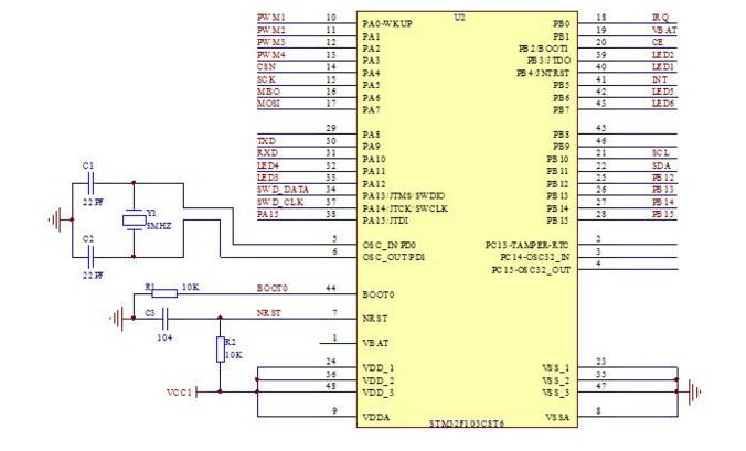
Considering both cost and performance, the main control units of both the flight control board and the remote control board use the enhanced high-speed microcontroller STM32F103 from STMicroelectronics as the main control unit. STM32F103 is based on the ARM 32-bit Cortex-M3 core architecture, with a stable operating frequency of up to 72M Hz. It is a microprocessor with rich resources and a high-speed clock that features a reduced instruction set. STM32F103 has optional flash program memory sizes of 64K or 128K bytes, up to 20K bytes of SRAM, two 12-bit analog-to-digital converters with up to 16 input channels, a 7-channel DMA controller, and up to 80 fast I/O ports. It supports serial single-wire debugging (SWD) and JTAG debugging modes, has up to 7 timers, up to 2 I2C interfaces (supporting SMBus/PMBus), up to 3 USART interfaces (supporting ISO7816, LIN, IrDA, and modem control), and up to 2 SPI interfaces (18M bits/second), as well as a CAN interface (2.0B active) and a USB2.0 full-speed interface.
The core design of the flight control board includes the MPU6050 measurement sensor, NRF2401 wireless module, and motor drive modules of the flight control board. The inertial measurement unit of the flight control system uses the MPU6050 as the measurement sensor, and the driving method of the MPU6050 adopts IIC10K interface. The clock pin SCL is connected to PB10 of the STM32, the data pin is connected to PB11 of the STM32, and the data interrupt pin is connected to PB5. To enhance driving capability, pull-up resistors are added to each pin.
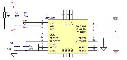
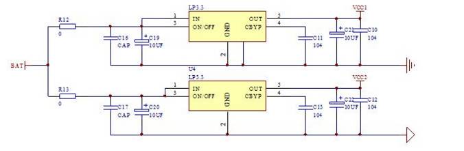
Relative to other modules, the power supply system is also a crucial part. The flight control system uses a 3.7V high discharge rate lithium battery for power supply. The power supply parts for the main control chip and the IMU sensor use separate independent LDO for power supply, ensuring the stability of the system and the accuracy of IMU sensor data acquisition.
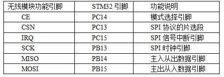
The communication of data between the flight control board and the remote control board also adopts the NRF2401 module based on the 2.4G frequency band, ensuring stable data transmission. The STM32’s SPI1 peripheral operates and drives the 2.4G module, with the pin connections shown in the table below:
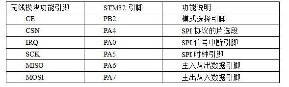
NRF2.4G uses a 3.3V powered wireless module, and the system uses the same power network as the microcontroller to power it, while adding a 0.1UF capacitor for filtering to ensure the module operates normally. The specific schematic connection of the wireless module is shown in the figure:
Remote Control Board Circuit Design The main control unit of the remote control board drives the 2.4G wireless module through the SPI bus, drives the 1602 LCD display through an 8-bit parallel port, collects joystick and battery voltage through ADC input pins, and drives a transistor switch to activate a buzzer for alerts. The core design of the remote control board includes the joystick simulation data acquisition module and the NRF2401 wireless module.
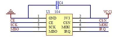
The joystick simulation data is collected using channels 4, 5, 6, and 7 of the ADC1 of the STM32 microcontroller and converted into digital signals, connected to pins PA4, PA5, PA6, and PA7, with filtering capacitors added to reduce noise signal interference. The schematic design of the joystick input for the remote control board is shown in the figure.
The NRF2.4G module’s driving uses the SPI2 peripheral of the STM32, with the connections of each functional pin shown in the table:
Software Design of the Quadcopter The software design of the quadcopter mainly includes the design of the flight control board software and the remote control board software. The overall software is written in C language within the MDK environment, and the ST-LINK emulator is used for debugging and downloading the program.
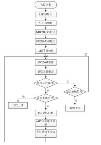
Flight Control Board System Software Design The main design concept of the flight control program is to initialize the wireless module, initialize the MPU6050, and initialize the PWM motors upon startup. Subsequently, the entire system IMU continues with zero bias processing, waiting for the unlock information to be transmitted. The flight control adopts a timer interrupt method, processing time within the interrupt. Each time the interrupt count flag increments, different accumulated interrupts correspond to different time intervals, handling tasks with varying priorities. The flowchart of the flight control system program design is shown in the figure:
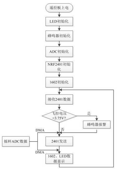
Remote Control Board System Software Design The role of the remote control board is to convert the operator’s actions into signals sent to the flight control board, while also displaying and processing some control information and data returned from the flight control board in real-time. The joystick data collection of the flight control board utilizes the ADC feature of the STM32, where the enhanced STM32F103xx product includes 2 embedded 12-bit analog-to-digital converters (ADC), each ADC sharing up to 16 external channels, enabling single or scanning conversions. Moreover, the STM32’s ADC can use DMA channels, which can further save hardware resources and improve system real-time performance. The SPI1 drives the NRF wireless module for data communication with the flight control board, and the system software flowchart of the remote control board is shown in the figure:
This system uses channels 4, 5, 6, and 7 of the ADC1 of the STM32 to collect joystick simulation data, and the configuration code for the ADC and DMA is as follows: ADC_Configuration(); //ADC function configuration DMA_Configuration(); //DMA function configuration The following is the code for starting the ADC and DMA: ADC_SOFtwareStartConvCmd(ADC1, ENABLE); //Start ADC1 conversion DMA_Cmd(DMA1_Channel1, ENABLE); //Start DMA channel Using the STM32 peripheral SPI1 to drive the NRF2.4G module, the SPI initialization code is as follows: Spi1_Init(); Using channel 40 of the wireless module for communication, the initialization function for the 2401 is as follows: Nrf24l01_Init(MODEL_RX2,40); //Channel 40 The reception function for the 2.4G wireless module NRF2401 is as follows: Nrf_Check_Event(); //Read NRF2401 data Sending control signals via 2401, the sending function is as follows: NRF_TxPACket_AP(NRF24L01_TXDATA_RC,32); //Send control signals to the quadcopter
This article describes the design and implementation of a simple quadcopter system. The entire scheme is divided into the remote control board and the flight control board, communicating via a 2.4G wireless module. The flight control system uses the IMU system to acquire attitude information and controls the motors based on feedback control algorithms to achieve flight control.
References:
[1] Li Yao. Design of Control System for Quadrotor UAV[D]. Dalian: Dalian University of Technology, 2016. [2] Tan Haoqiang. C Programming Tutorial[M]. Beijing: Tsinghua University Press, 2010.
[3] Liu Huoliang. Practical Guide to STM32 Library Development[M]. Beijing: Machinery Industry Press, 2013. [4] Bai Zhigang. Analysis of Automatic Adjustment Systems and PID Tuning[M]. Beijing: Chemical Industry Press, 2015.[5] Zhu Jun. Design and Control Method Research of Quadrotor UAV Control System[D]. Inner Mongolia: Inner Mongolia University of Science and Technology, 2015.