For electronic engineers, extracting maximum performance from circuits is crucial, especially for Analog-to-Digital Converters (ADC). Among these, resolution is one of the key indicators for optimal ADC performance. However, once the ADC and its reference voltage are determined, the highest resolution achievable in a single sample seems to be a fixed limit.
For example, with a common 10-bit ADC paired with a 5V reference voltage, the theoretical resolution is as follows:
5V / (210 – 1) = 5V / 1023 ≈ 4.888mV / bit (step)
However, if this ADC system is used to measure a sensor with an output range of 0~1V, the actual usable resolution is approximately 205 effective steps (1V / 4.888mV), resulting in an effective resolution significantly reduced to 1/205. This not only leads to insufficient data accuracy but also greatly diminishes practical value.
For instance, if such a device is designed to measure the voltage changes across an inductor during a DC step voltage, the error curve will become more pronounced (Figure 1). In the first few seconds, significant data changes can be observed, but afterward, the curve flattens, causing many ADC sample values to repeat, leading to increased relative error.
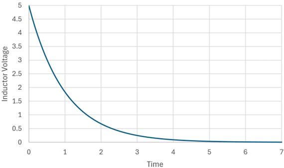
Figure 1: The voltage curve measured over time when a DC step voltage is applied across an inductor in series with a resistor. Note that after 3 seconds, the slope flattens, leading to increased relative error.
To address this, there are two basic methods to improve resolution:
-
Use a higher resolution ADC (e.g., 12, 14, or 16 bits)
-
Lower the reference voltage of the ADC
Of course, advanced techniques such as delta-sigma ADCs can also be employed. However, changing the resolution typically means adding an external ADC or replacing the microcontroller (MCU), which increases costs and design complexity.
A smarter choice: Adaptive Resolution
If you do not want to replace the ADC or MCU, let the reference voltage adjust dynamically! This is the core idea of Adaptive Resolution. But how can a system be designed to automatically adjust the reference voltage?
Implementing Adaptive Reference Voltage with Arduino Nano
In this demonstration, the simplest way is to use the Arduino Nano, which supports the ATMEGA328P MCU. It supports three sources for ADC reference voltage:
-
Vcc (typically +5V)
-
Internal 1.1V reference voltage
-
External reference voltage pin (REF pin)
The operational logic is as follows: first, use an analog input pin (e.g., A0, which can connect to the 10-bit ADC) to measure the voltage or read the sensor voltage. The trick is to set the reference voltage to Vcc (this design uses 5V) and read the ADC readings from the analog input.
If the converted voltage is less than 1.1V, switch the reference voltage to the internal 1.1V and resample. If the voltage rises to 1.1V or above, switch back to 5V as the reference voltage.
Since the sensor’s rate of change is usually lower than the sampling frequency, this switching can provide higher resolution. Figure 2 shows how this logic applies to the changes in inductor voltage.
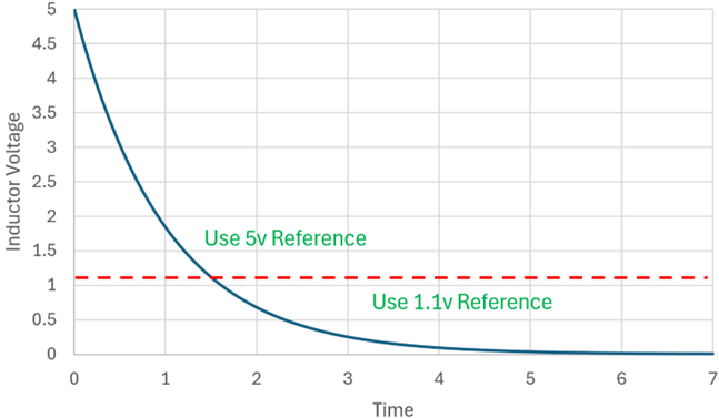
Figure 2: The ATMEGA328P uses 5V and 1.1V as switchable reference voltages, dynamically changing resolution based on input voltage changes.
This method is particularly suitable for slowly varying input signals, such as temperature sensors or inductive analysis. When the input voltage decreases, a smaller reference voltage is automatically used to obtain more detailed data.
Adaptive Resolution Program Code
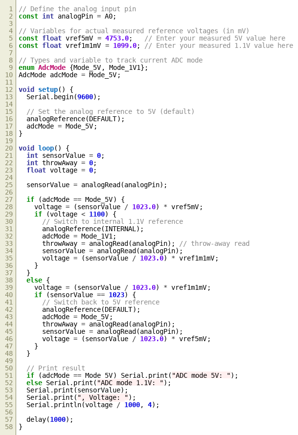
The following is the C language program code used to demonstrate the concept of adaptive resolution.
Note: This basic program code was initially written by Microsoft Copilot AI, performing quite well with clear variable naming, adequate comments, and a clean layout, correctly converting ADC digital values to corresponding analog voltages. However, when I attempted to add further logic, the results produced by Copilot became somewhat chaotic, so subsequent logic modifications and program organization were manually written by me.
Key to Precision: Pre-calibrating Reference Voltage
The program will continuously read the ADC value from the analog pin A0, initially using 5V as the reference voltage. If the A0 reading converted is <1.1V, it switches to the internal 1.1V reference voltage to obtain higher resolution data. If the reading reaches 1023, indicating an input voltage ≥1.1V, it switches back to the 5V reference. The program will output the reference voltage used and the corresponding measurement results.
To obtain accurate voltage readings, it is recommended to use a high-precision voltmeter (such as a 5½ digit digital multimeter) to measure the actual values of Vcc and the internal 1.1V accurately, and write them into the program variables.
Comparison of Relative Errors between 1.1V and 5V Reference Voltages
Please note that at the top of the program code, when the input on A0 is greater than 1.1V, the 5V reference voltage variable (referenceVoltage 5V) is set to the actual voltage measured at the Arduino Nano REF pin. When the A0 voltage is less than 1.1V, the voltage at the REF pin should also be measured to set the 1.1V reference voltage variable (referenceVoltage1p1V), so that it corresponds to the correct voltage value after digital conversion. Figure 3 illustrates this concept.
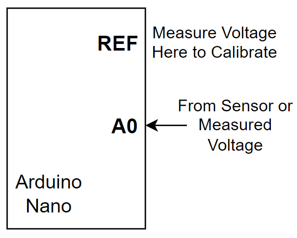
Figure 3: The program continuously reads A0. If the voltage < 1.1V, it switches to the 1.1V reference; if > 1.1V, it uses the 5V reference.
Through the following sets of data, the actual improvement effect brought by the adaptive resolution mechanism can be displayed: when the input voltage approaches 1.1V, if 5V is used as the reference voltage, the parsing error can be as high as 0.41%; if 1.1V is used as the reference, the error can be reduced to 0.10%. When the input is 100mV, the error using 5V reference voltage may reach 4.6%; using 1.1V reference voltage can control it within 1.1%. If the input signal is as low as 10mV, the error with 5V as reference may soar to 46%, while the 1.1V reference can reduce the error to below 10.7%.
This data clearly shows that in the low voltage range, resolution is closely related to the reference voltage. By switching the reference voltage according to the input voltage, measurement accuracy can be significantly improved.
Further Expanding Reference Voltage Levels
If further resolution enhancement or a wider input range is needed, consider using more reference voltage levels. However, due to the precision limits of 10-bit ADCs, it is recommended not to exceed 3 to 4 levels of reference voltage, or else diminishing returns will be encountered.
Here are three practical ways to expand:
External DAC Providing Multiple Reference Voltages
The first method is to use an external Digital-to-Analog Converter (DAC), connecting its output to the REF pin of the Arduino Nano as an adjustable reference voltage source for the ADC. This DAC is controlled by the Nano and can switch between multiple reference voltages. For example, the MAX5362 DAC controlled via I²C provides a reference voltage of 0.9 × Vcc, with a maximum output of about 4.5V. In this design, the REF pin of the Nano needs to be set to EXTERNAL mode (as shown in Figure 4).
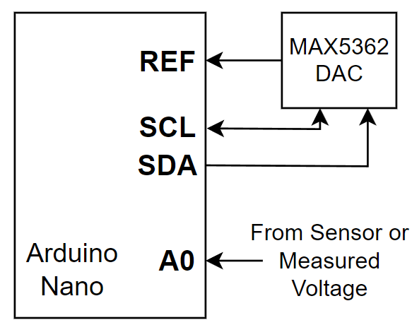
Figure 4: Using the MAX5362 DAC as an external reference voltage, controlled by the Arduino Nano to switch different reference levels.
Using PWM Output with Low-Pass Filter
The second method is to output multiple DC reference voltages through PWM. The PWM pins of the Arduino Nano can output high-speed signals, which, after passing through a low-pass filter (RC or multi-stage filter), produce a stable DC voltage. It is best to choose high-frequency PWM and ensure good filtering, with ripple voltage ideally below 1mV (approximately -74dB). Each PWM output corresponds to a different voltage group, requiring actual measurement for program calibration. This method is low-cost and highly flexible, but requires practical measurement calibration and good filtering.
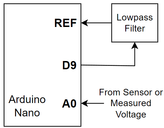
Figure 5: Using PWM output from the Arduino Nano with a low-pass filter to generate a clean DC voltage signal as ADC reference.
Resistor Ladder Method with Analog Switch
The third method is to construct a resistor ladder and then use a multi-channel analog switch (such as TI TMUX1204) to switch between different voltage divider nodes to obtain multiple reference voltages. The digital output pins of the Arduino Nano can be used to control the position of the analog switch, switching between different voltage nodes. The resistor values in the ladder should be configured and calibrated according to the target reference voltage. This method is highly stable and suitable for fixed multi-segment range applications.
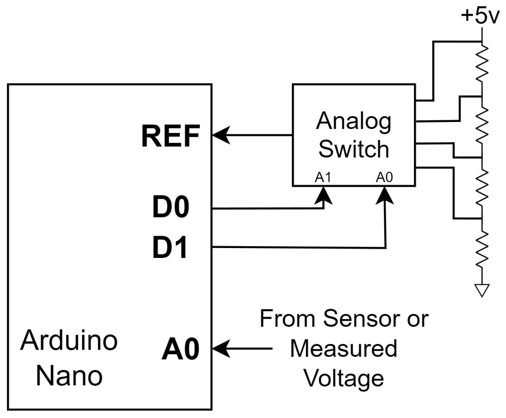
Figure 6: Using a resistor ladder with an analog switch (such as TI TMUX1204) to switch between different voltage nodes to generate multiple reference voltages.
Conclusion: The Value of Engineers
Whether it is low-cost PWM filtering or highly flexible DAC control, the purpose of these methods is to break through hardware limitations and achieve high precision through software intelligence. Although various methods offer different cost and precision options, their core concept is consistent: enhancing the effective resolution and accuracy of the ADC through multiple reference voltages.
While such designs may seem like “just solving problems that haven’t arisen yet,” isn’t that the essence of an engineer’s work? – To preemptively combine potential problems with solutions, creating more reliable and accurate systems.
Editor: Ricardo