Source | Renesas Embedded EncyclopediaDue to the speed advantages of the CAN bus and its widespread application, it is essential to understand or master some basic knowledge of CAN in embedded development..
1. Overview
CAN (Controller Area Network) and CANFD (Controller Area Network Flexible Data-rate) are communication protocols commonly used in automotive and industrial fields.
The CAN protocol was originally developed by Bosch in Germany in the 1980s to address the communication needs of automotive electronic devices. It is an efficient and reliable serial communication protocol that supports high-speed data transmission over short distances. The CAN protocol operates on an event-triggered basis, allowing multiple devices to participate in communication simultaneously and ensuring real-time and reliable data transmission through a priority mechanism. Classic CAN, sometimes referred to as standard CAN or ordinary CAN, is a widely recognized version of this protocol.
The characteristics of the CAN protocol include:
Twisted Pair: The CAN bus consists of two transmission lines, CAN_H and CAN_L, which transmit data using differential signals to enhance anti-interference performance.
Collision Detection and Resolution: When multiple devices send data simultaneously, the CAN protocol can detect collisions and resolve them through a priority mechanism.
Simple Frame Format: CAN messages consist of an ID, data, control bits, and CRC checks, resulting in low overhead and high data transmission efficiency.
Strong Fault Tolerance: The CAN protocol employs bit-level error detection and recovery mechanisms, enabling highly reliable data transmission.
With the development of automotive electronic systems and the increasing demand for data communication, the CANFD protocol emerged. CANFD retains the basic characteristics of the CAN protocol while introducing new features, primarily enhancements in data transmission rates and data lengths. Compared to the traditional CAN protocol, CANFD supports higher data transmission rates (up to 8 Mbps) and larger data lengths (up to 64 bytes). This allows CANFD to meet the requirements of applications with higher data bandwidth demands, such as Advanced Driver Assistance Systems (ADAS) and autonomous driving.
The CAN FD protocol was developed through research by Bosch and industry experts and was released in 2012. It has been standardized and is now included in ISO 11898-1:2015. The original Bosch CAN FD version (non-ISO CAN FD) is not compatible with ISO CAN FD. CAN FD has four main advantages:
Increased Data Length: CAN FD supports up to 64 data bytes per data frame, while traditional CAN supports a maximum of 8 data bytes. This reduces protocol overhead and improves protocol efficiency.
Increased Transmission Speed: CAN FD supports dual bit rates; like traditional CAN, the nominal (arbitration) bit rate is limited to 1 Mbit/s, while the data bit rate depends on the network topology/transceiver. In practice, data bit rates of up to 5 Mbit/s can be achieved (up to 8 Mbit/s in actual applications, but without standardization).
Better Reliability: CAN FD uses improved cyclic redundancy check (CRC) and a “protected fill bit counter,” reducing the risk of undetected errors. This is crucial in safety-critical applications such as automotive and industrial automation.
Smooth Transition: In certain cases, CAN FD can be used on ECUs that only use traditional CAN, allowing for a gradual introduction of CAN FD nodes, thereby simplifying programs and reducing costs for OEMs.
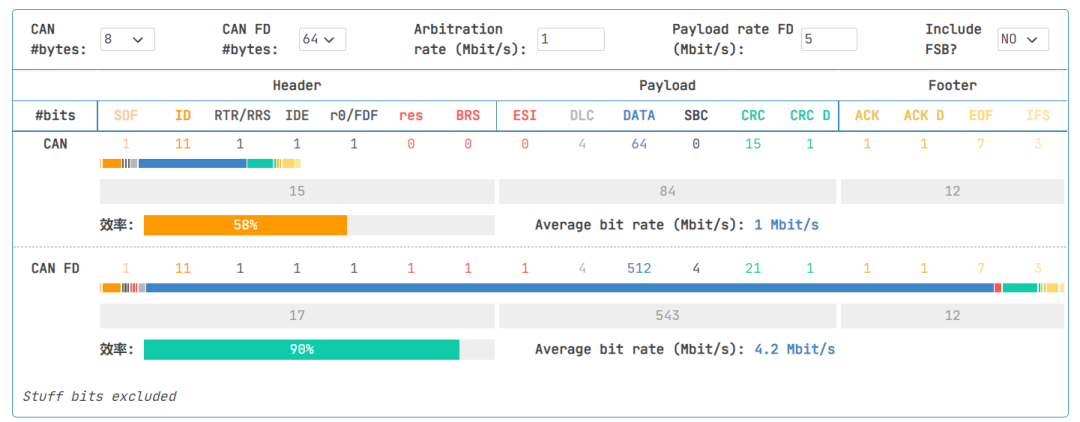
Compared to traditional CAN, CAN FD can increase network bandwidth by 3 to 8 times, improving efficiency from 50% to 90%, thus providing a simple solution for data growth.
2. CAN Protocol
2.1 Physical Layer
Unlike synchronous communication methods like I2C and SPI that use clock signals, CAN communication does not synchronize using clock signals; it is an asynchronous communication method that only has two signal lines, CAN_High and CAN_Low, forming a differential signal pair for communication.
The physical layer of CAN primarily has two forms: closed-loop bus networks and open-loop bus networks.
2.1.1 Closed-loop Bus Network
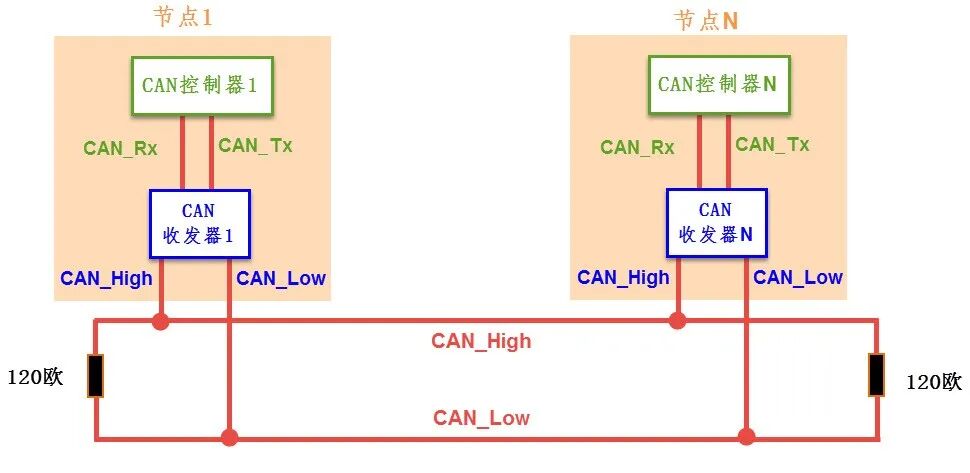
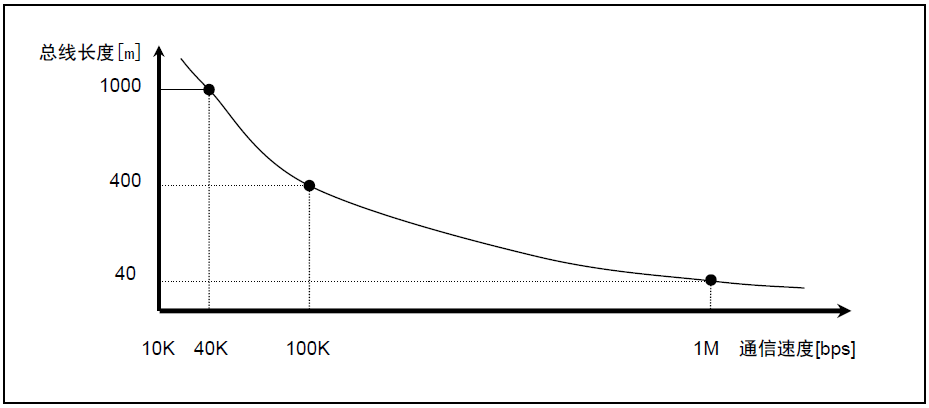
The CAN communication network shown in the figure below is a high-speed, short-distance “closed-loop network” that complies with the ISO11898 standard, with a maximum bus length of 40m and a maximum communication speed of 1Mbps. Each end of the bus requires a “120-ohm” resistor.
2.1.2 Open-loop Bus Network
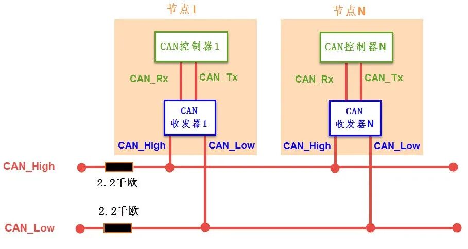
The figure below shows a low-speed, long-distance “open-loop network” that complies with the ISO11519-2 standard, with a maximum transmission distance of 1km and a maximum communication rate of 125kbps. The two buses are independent and do not form a closed loop, requiring a “2.2k-ohm” resistor to be connected in series on each bus.
2.1.3 Differences Between ISO11898 (Closed-loop Bus Network) and 11519-2 (Open-loop Bus Network) Protocols
The ISO11898 and ISO11519-2 standards have the same definition for the data link layer, but differ in the physical layer.
ISO11898 is the high-speed communication standard for CAN with communication speeds of 125kbps-1Mbps.
ISO11519 is the low-speed communication standard for CAN with communication speeds below 125kbps.
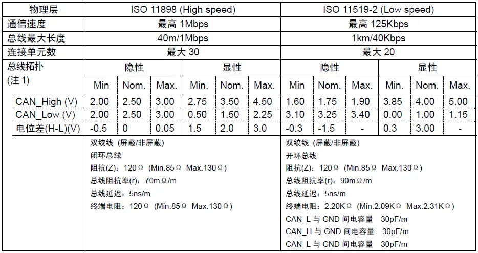
The following figure describes the main differences in the physical layers of ISO11898 and 11519-2.
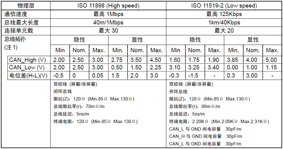
Users need to set the communication speed and bus length according to system requirements.
2.1.4 Differential Signals in the CAN Protocol
Differential signals, also known as differential mode signals, differ from traditional methods that use a single signal line voltage to represent logic. When transmitting using differential signals, two signal lines are required, with equal amplitudes and opposite phases, representing logic 0 and logic 1 through the voltage difference between the two signal lines.
The CAN protocol specifies the differential signals represented by CAN_High and CAN_Low. The signal logic defined by the CAN protocol is shown in the table below.
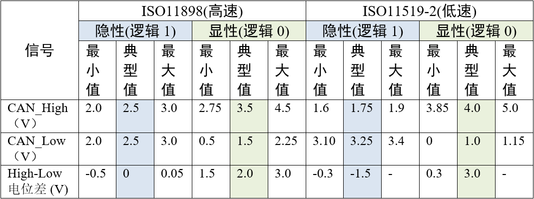
For example, in the high-speed CAN protocol, when representing logic 1 (recessive level), the voltage on both CAN_High and CAN_Low lines is 2.5V, meaning their voltage difference VH-VL=0V; when representing logic 0 (dominant level), the level of CAN_High is 3.5V, and the level of CAN_Low is 1.5V, resulting in a voltage difference of VH-VL=2V. For instance, when the CAN transceiver receives a low-level signal (logic 0) from the CAN controller via the CAN_Tx line, it will output 3.5V on CAN_High and 1.5V on CAN_Low, thus outputting a dominant level representing logic 0.
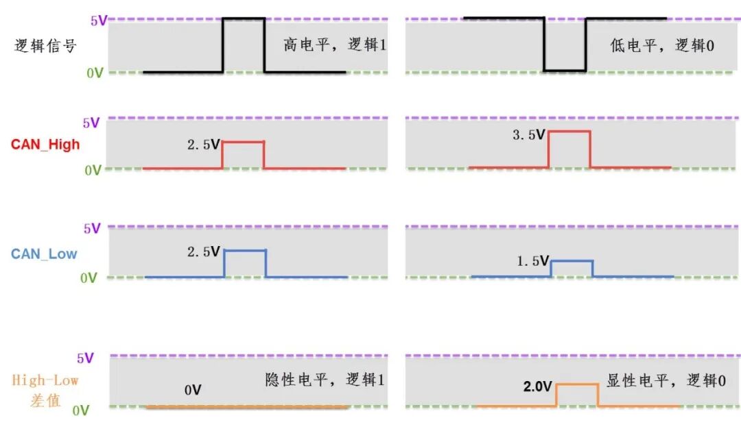
In the CAN bus, it must be in either a recessive level (logic 1) or a dominant level (logic 0) at any given time. If there are two CAN communication nodes, and at the same time one outputs a recessive level while the other outputs a dominant level, the “wired AND” characteristic similar to the I2C bus will cause it to be in a dominant level state, hence the name dominant level, which implies priority.
Since the physical layer of the CAN bus only has one pair of differential lines, it can only represent one signal at a time, making CAN communication half-duplex, requiring time division for data transmission. In the CAN communication network, because of the shared bus, only one communication node can send a signal at any given time, while the others can only receive.
2.2 Protocol Layer
The previous section discussed the physical layer standards of CAN, which define electrical characteristics. The following introduces the protocol layer, which specifies communication logic.
2.2.1 Types of Frames
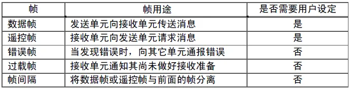
Communication is conducted through the following five types of frames.
• Data Frame
• Remote Frame
• Error Frame
• Overload Frame
• Frame Interval
Among these frames, data frames and remote frames are set by the user, while the other frames are handled by the hardware part of CAN.
Additionally, data frames and remote frames have both standard and extended formats. The standard format has an 11-bit ID, while the extended format has a 29-bit ID.
The purposes of various frames are shown in the table below.
2.2.2 Data Frame
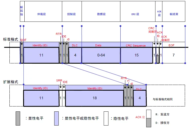
The data frame transmits messages from the sending unit to the receiving unit and is the most basic frame used by users. The data frame consists of seven segments.
(1) Frame Start: Indicates the beginning of the data frame.
(2) Arbitration Segment: Indicates the priority of the frame.
(3) Control Segment: Indicates the number of data bytes and reserved bits.
(4) Data Segment: The data itself, which can transmit 0 to 8 bytes.
(5) CRC Segment: Checks for transmission errors in the frame.
(6) ACK Segment: Acknowledgment segment for normal reception.
(7) Frame End: Indicates the end of the data frame.
2.2.3 Remote Frame
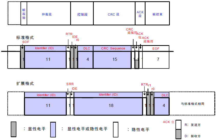
The remote frame is used by the receiving unit to request messages from the sending unit. The remote frame consists of six segments and can be considered a data frame without a data segment.
(1) Frame Start (SOF): Indicates the start of the frame.
(2) Arbitration Segment: Indicates the priority of the frame. Requests a data frame with the same ID.
(3) Control Segment: Indicates the number of bytes of the requested data and reserved bits.
(4) CRC Segment: Checks for transmission errors in the frame.
(5) ACK Segment: Acknowledgment segment for normal reception.
(6) Frame End: Indicates the end of the remote frame.
Regarding remote frames and data frames:
• What is the difference between data frames and remote frames?
The remote frame does not have a data segment, and the RTR bit in the arbitration segment is recessive.
• How is the data length code represented in a remote frame without a data segment?
The data length code of the remote frame is represented by the data length code of the requested data frame.
• What is the purpose of a data frame without a data segment?
It can be used for periodic connection confirmations/responses between units or when the arbitration segment itself carries substantial information.
2.2.4 Error Frame
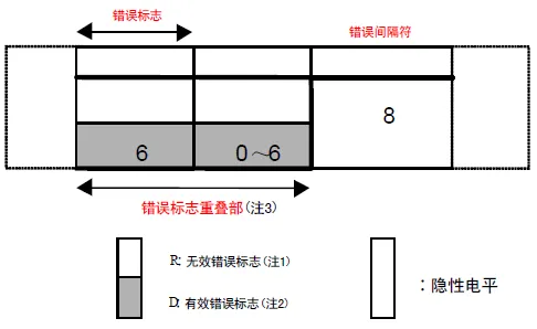
The error frame is used to notify errors detected during transmission. The error frame consists of an error flag and an error delimiter, and its transmission is handled by the hardware part of CAN.
(1) Error Flag: The error flag includes both valid and invalid error flags.
• Valid Error Flag: 6 bits of dominant level.
• Invalid Error Flag: 6 bits of recessive level.
(2) Error Delimiter: The error delimiter consists of 8 bits of recessive level.
Note
1. Valid Error Flag: The error flag transmitted when a unit in the error active state detects an error.
2. Invalid Error Flag: The error flag transmitted when a unit in the error passive state detects an error.
3. Overlapping of Error Flags: Due to different error detection times of the units connected to the bus, error flags may overlap, lasting up to 12 bits.
2.2.5 Overload Frame
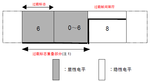
The overload frame is used to notify the sending unit that it is not yet ready. The overload frame consists of an overload flag and an overload delimiter.
(1) Overload Flag: 6 bits of dominant level. The structure of the overload flag is the same as that of the valid error flag.
(2) Overload Delimiter: 8 recessive bits. The structure of the overload delimiter is the same as that of the error delimiter.
Note
1. Overload Frame Overlap: Similar to error flags, overload flags may also overlap based on the timing of occurrence, lasting up to 12 bits.
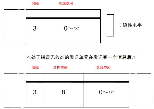
2.2.6 Frame Interval
The frame interval is used to separate data frames or remote frames. Inserting a frame interval before a data frame or remote frame can separate it from any previously sent frame (data frame, remote frame, error frame, overload frame). However, a frame interval cannot be inserted before overload frames and error frames.
(1) Interval: 3 recessive bits. If a dominant level is detected during the “interval” period, an overload frame must be sent. However, if a dominant level appears in the 3rd bit of the interval, it is considered SOF, and no overload frame is sent.
(2) Bus Idle: Recessive level, with no length limit (0 bits is also acceptable). This state indicates that the bus is idle, and the unit that wants to send can start sending messages.
(3) Delayed Transmission (Temporary Stop of Sending): 8 recessive bits. This segment must be included in the frame interval after a unit in the error passive state sends a message.
2.2.7 Priority Arbitration
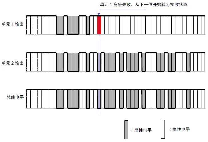
In the bus idle state, the unit that starts sending the message first gains communication rights.
When multiple units start transmitting simultaneously, each sending unit begins arbitration from the first bit of the arbitration segment. The unit with the first differing bit level that is dominant gains communication rights to send. The units that fail arbitration enter receive mode at the next bit.
The arbitration process is illustrated in the figure below:
(1) Priority of Data Frames and Remote Frames
When data frames and remote frames with the same ID compete on the bus, the data frame with the last bit of the arbitration segment (RTR) as a dominant level has priority and can continue communication.
(2) Priority of Standard Format and Extended Format
When standard format and extended format data frames or remote frames with the same base ID compete on the bus, the standard format has higher priority due to its RTR bit being dominant, allowing it to be sent.
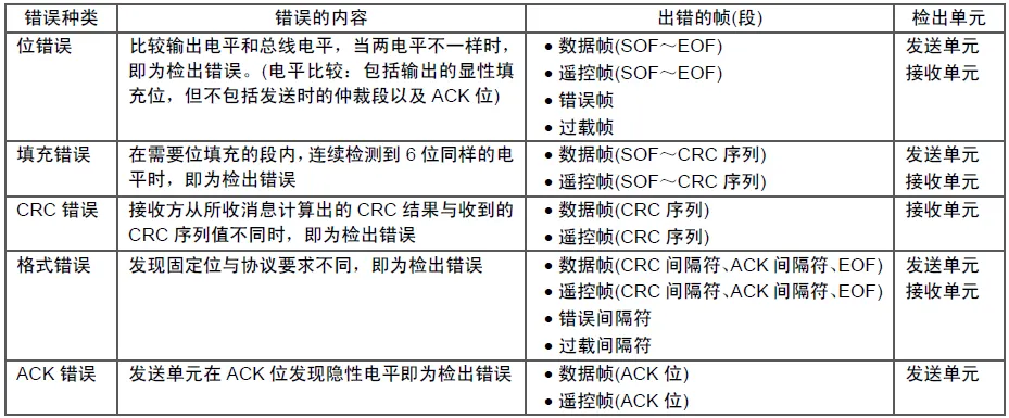
2.2.8 Types of Errors
There are five types of errors. Sometimes multiple errors may occur simultaneously.
• Bit Error
• Stuffing Error
• CRC Error
• Format Error
• ACK Error
The types of errors, their contents, the erroneous frames, and the units that detected the errors are shown in the table below.
2.2.9 Bit Timing
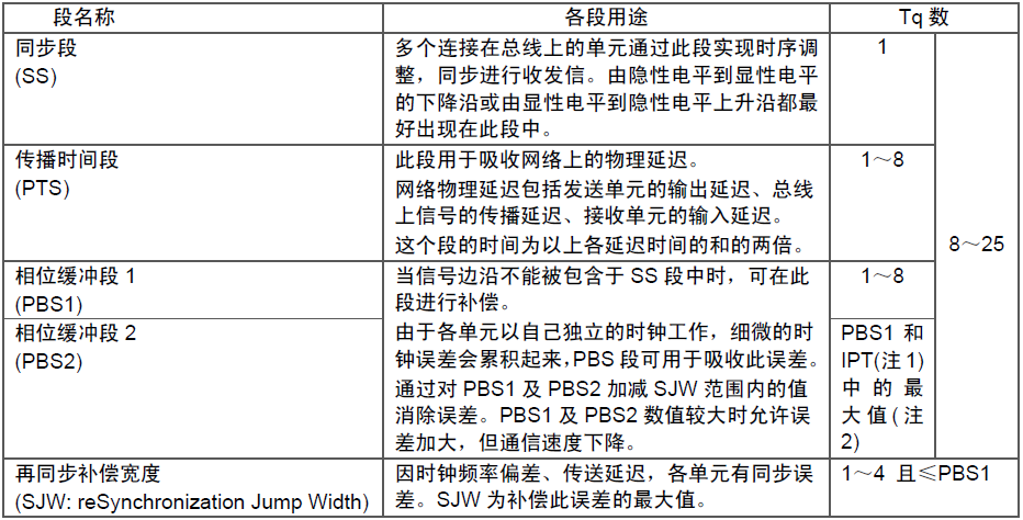
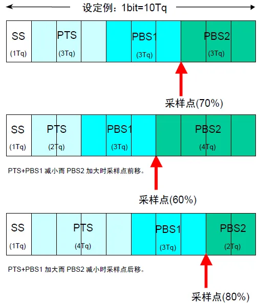
A bit can be divided into four segments.
• Synchronization Segment (SS: Synchronization Segment)
• Propagation Time Segment (PTS: Propagation Time Segment)
• Phase Buffer Segment 1 (PBS1: Phase Buffer Segment 1)
• Phase Buffer Segment 2 (PBS2: Phase Buffer Segment 2)
These segments are composed of the minimum time unit Tq (Time Quantum).
A single bit in a message is divided into four segments, each of which consists of several Tq units, referred to as bit timing.
The number of Tq units that make up a bit and how many Tq units each segment consists of can be set arbitrarily. By setting the bit timing, multiple units on the bus can sample messages at the same timing, allowing for the setting of sample points. The sample point is set at the end of PBS1, using the voltage value detected on the bus at that time as the bit value.
The purposes of each segment and the number of Tq units are shown in the table below.
The composition of a single bit is illustrated in the figure below.
2.2.10 Synchronization Methods
The communication method of the CAN protocol is Non-Return to Zero (NRZ). There are no start or end synchronization signals for each bit. The sending unit begins sending data in synchronization with the bit timing. The receiving unit synchronizes the received signal based on the voltage changes on the bus.
However, clock frequency errors between the sending and receiving units and phase delays in the transmission path (cables, drivers, etc.) can cause synchronization deviations. Therefore, the receiving unit adjusts the timing for reception through forced synchronization and resynchronization methods.
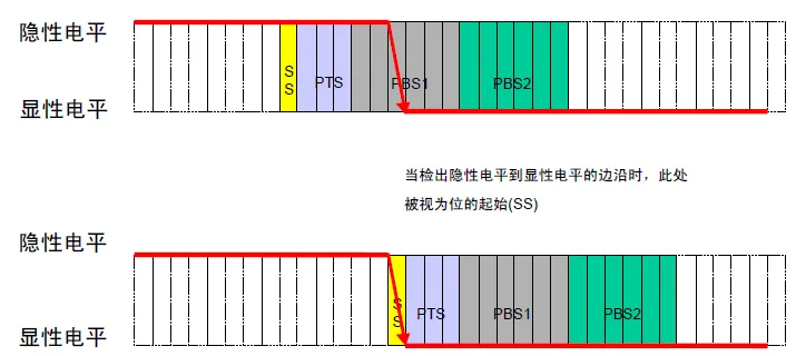
2.2.11 Forced Synchronization
Forced synchronization is performed by the receiving unit when it detects the frame start in the bus idle state. Detecting the edge from recessive level to dominant level is considered the SS segment, independent of SJW.
2.2.12 Resynchronization
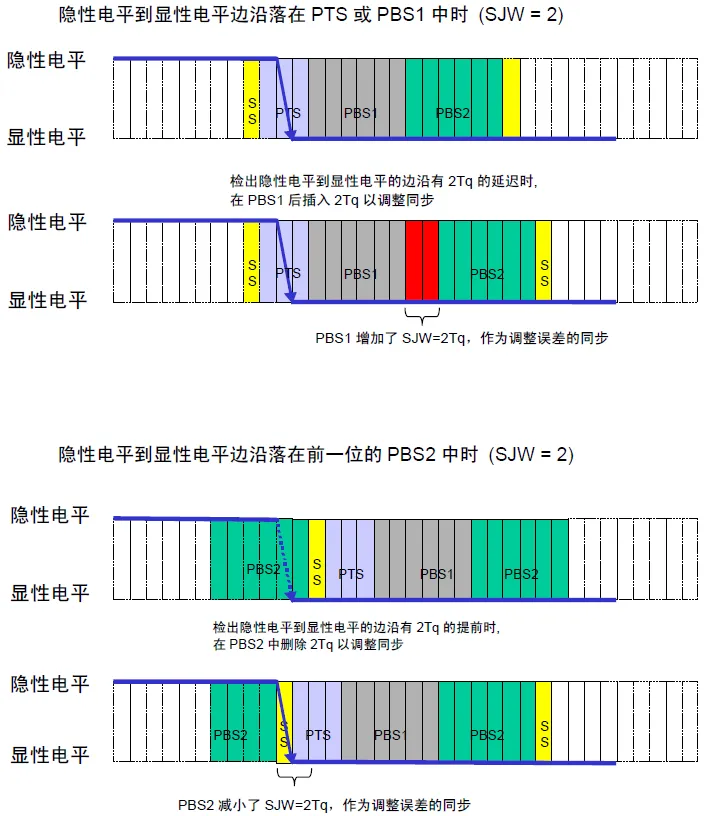
Resynchronization is performed during reception based on voltage changes on the bus.
When detecting an edge (voltage transition on the bus), the timing is adjusted according to the error value, extending the PBS1 segment or shortening the PBS2 segment to synchronize. However, if an error exceeding the SJW value occurs, corrections are made according to the SJW value.
2.2.13 Synchronization Rules
Forced synchronization and resynchronization follow these rules.
(1) Synchronization adjustments are made only once within a single bit (between two sample points).
(2) An edge can only be used for synchronization if the bus level after the edge differs from the bus sample value before the edge.
(3) Once an edge from recessive level to dominant level is detected, synchronization must occur if conditions (1) and (2) are met.
(4) If an edge from recessive level to dominant level is detected during the frame interval (excluding the first bit of the “interval”), forced synchronization must occur.
(5) All other edges from recessive level to dominant level must undergo resynchronization.
(6) The sending unit does not perform resynchronization when it observes a delay in its own output of the dominant level.
2.3 CANFD Frame
CAN FD can be understood as an upgraded version of the CAN protocol, with only the protocol upgraded while the physical layer remains unchanged.
The CAN FD protocol introduces adjusted CAN data frames to achieve additional data bytes and flexible bit rates.
Below, we compare an 11-bit traditional CAN frame with an 11-bit CAN FD frame (which also supports 29 bits):

Next, we will discuss these differences step by step:
RTR and r1 (RRS): In traditional CAN, the Remote Transmission Request (RTR) is used to identify data frames and corresponding remote frames. However, in CAN FD, remote frames are not supported, and the remote request replacement (r1) is always dominant (0).
In the CAN-FD frame, three new bits (FDF, BRS, ESI) are added to the control field:
• Extended Data Length (EDL): Recessive indicates the frame is CAN-FD; otherwise, this bit is dominant (referred to as R0) in CAN 2.0 frames. In frames of traditional CAN format, the corresponding transmission is bit R0 rather than EDL.
• Bit Rate Switch (BRS): Indicates whether to enable two bit rates. If recessive, the bit rate switches from the standard bit rate during the arbitration phase to the pre-configured alternate bit rate during the data phase. If dominant, the bit rate does not switch.
• Error State Indicator (ESI): Indicates the status of the sending node, indicating whether the node is in error active mode or error passive mode.
DLC: Like in traditional CAN, the CAN FD DLC is 4 bits, indicating the number of data bytes in the frame. The table below shows how both protocols can always use up to 8 data bytes of DLC. To maintain a 4-bit DLC, CAN FD uses the remaining 7 values from 9 to 15 to represent the number of data bytes used (12, 16, 20, 24, 32, 48, 64).
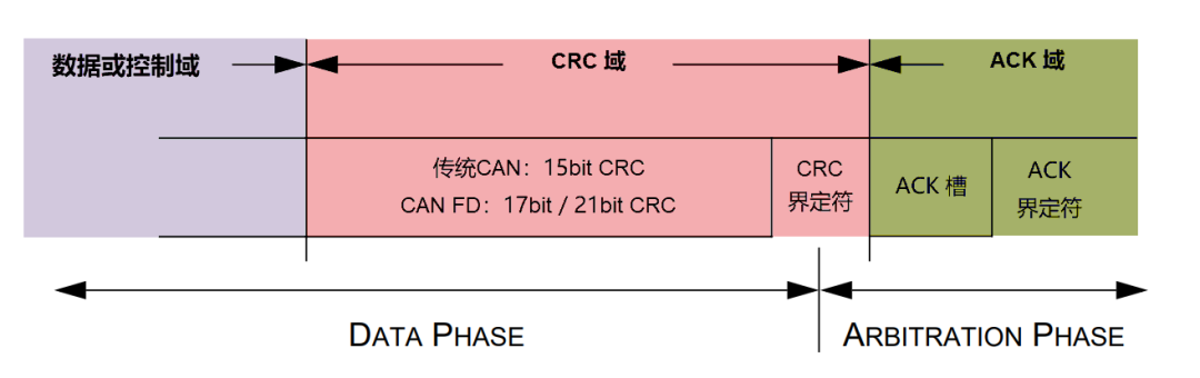
CRC: The cyclic redundancy check (CRC) in traditional CAN is 15 bits, while in CAN FD it is 17 bits (for up to 16 data bytes) or 21 bits (for 20-64 data bytes). In traditional CAN, the CRC may include 0 to 3 stuffing bits, while in CAN FD, there are always four fixed stuffing bits to enhance communication reliability.
In summary, the CAN and CANFD protocols are communication protocols commonly used in automotive and industrial fields. The CAN protocol is an efficient and reliable serial communication protocol, while the CANFD protocol enhances data transmission rates and data lengths while retaining the basic characteristics of the CAN protocol. Both protocols play a crucial role in vehicle electronic systems, enabling reliable communication between various electronic devices within the vehicle.
———— END ————
Renesas Embedded Development | Common Tools for Renesas MCU Development
What are Reality AI tools applied to MCU/MPU?
Adding Keil AC6 Compiler in the MCU Integrated Development Environment e2 studio