Before looking at various wiring diagrams, let’s first understand the functions of PLCs, servo drives, inverters, and motors.
When we enter a modern factory, we often see various complex control cabinets filled with different electrical devices. PLCs, servo drives, inverters, motors… these terms may sound like advanced technology to non-professionals. However, their core principles are much simpler than one might think.
We can use the following analogy for the entire system:
-
PLC (Programmable Logic Controller) = Brain
-
Servo Drive/Inverter = Central Nervous System
-
Motor = Muscle
Next, we will introduce these components in the simplest terms:
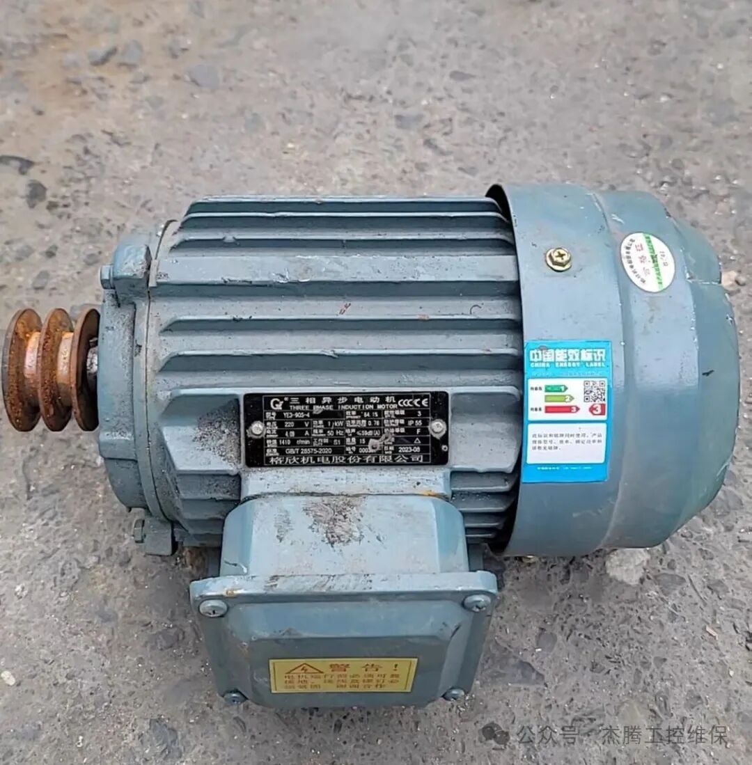
Motor
Motor, commonly referred to as a motor, is a device that converts electrical energy into mechanical energy. In simple terms, the motor is the component that makes the equipment “rotate.” Motors can be categorized into ordinary motors, stepper motors, servo motors, etc. Among these, ordinary motors are easier to repair, while the others are more challenging to fix when they fail.
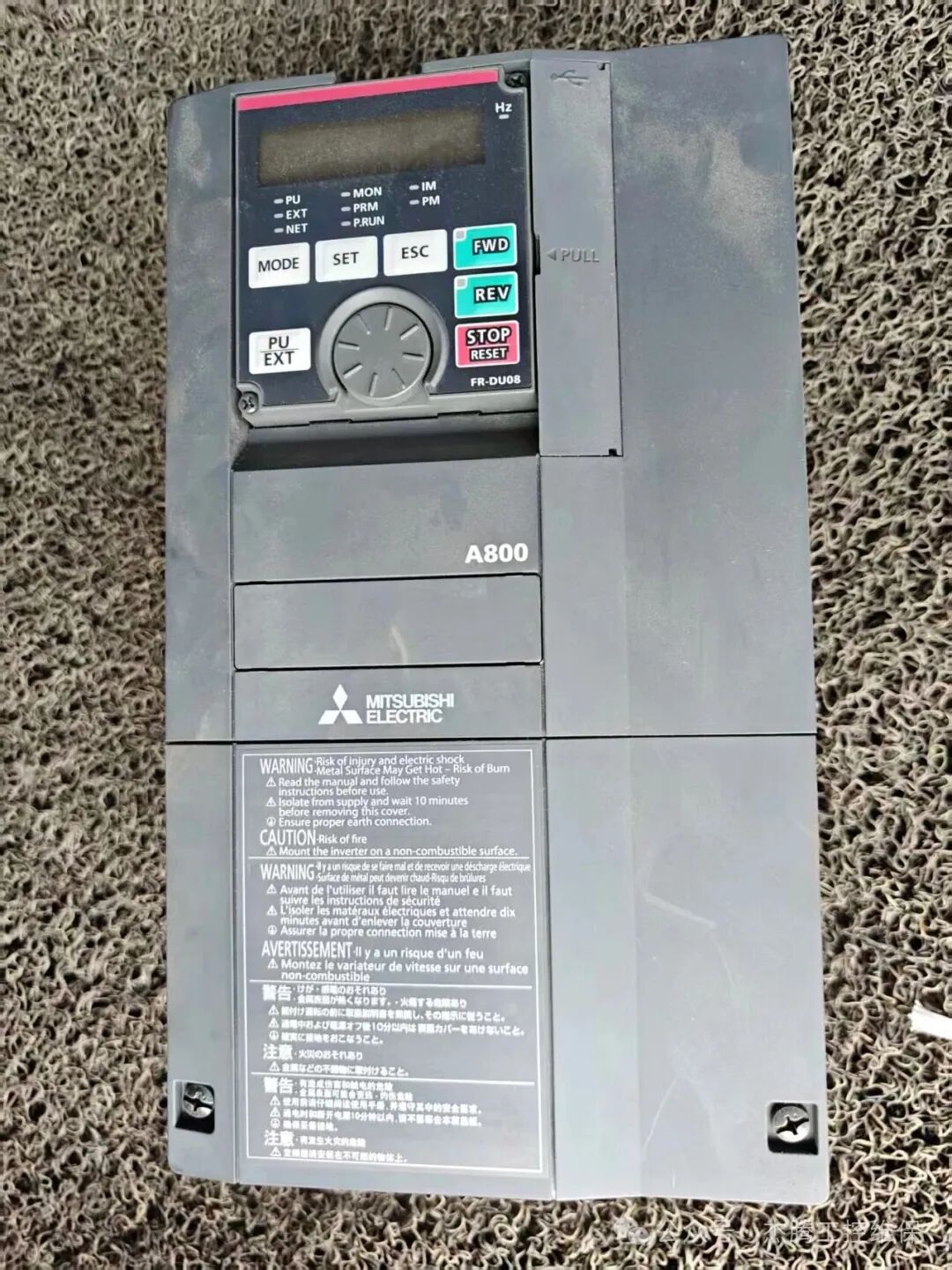 Inverter
Inverter is the “speed regulator” of the motor,
As the name suggests, an inverter is a device that changes the operating frequency of the motor.It controls the speed of ordinary motors by adjusting the power supply frequency.
Without an inverter, the motor can only operate at a fixed speed, either full speed or stop. With an inverter, we can run the motor at any speed, achieving smooth start and stop, greatly saving energy and reducing mechanical shock.
For example, inverters are commonly used in fans, water pumps, escalators in shopping malls, and CNC equipment in factories. Popular inverter brands on the market include Siemens, Schneider, ABB, Delta, Inovance, and Yaskawa.
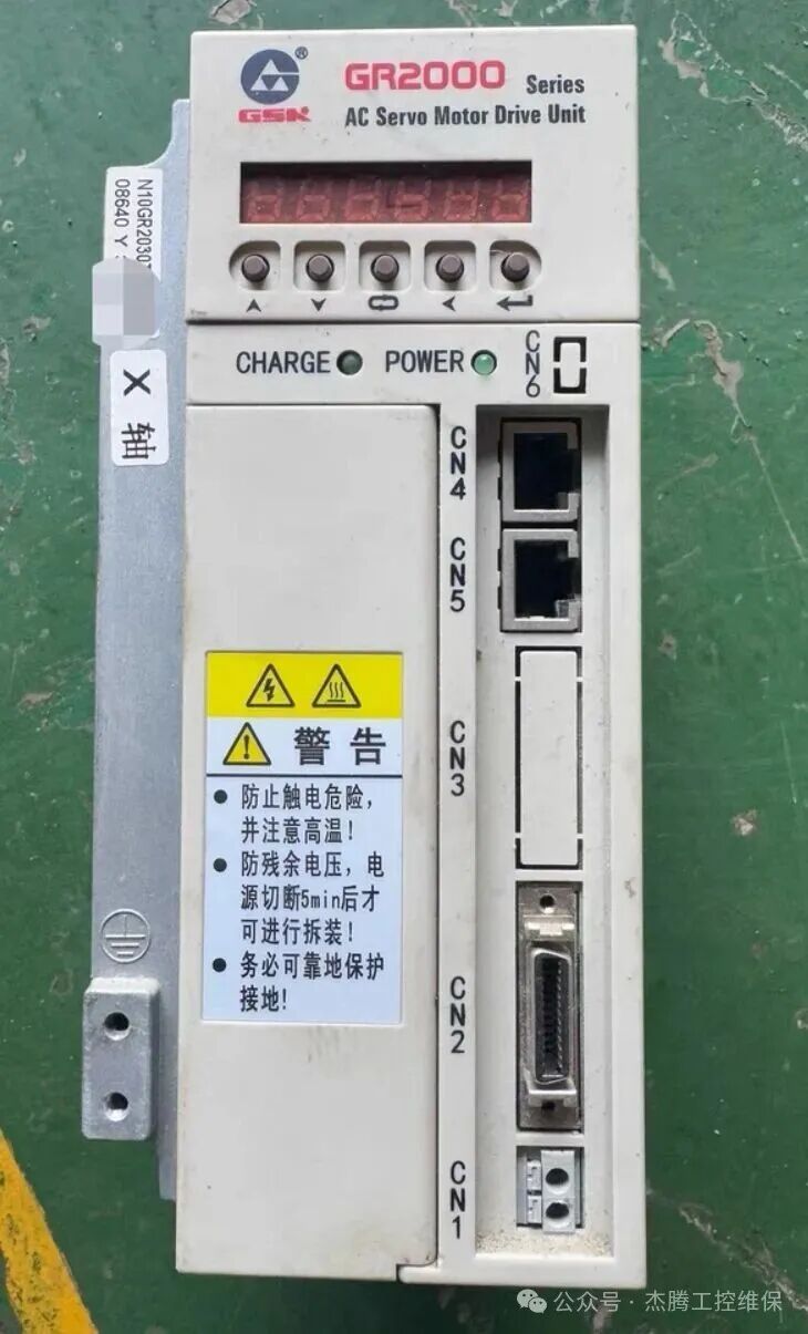
Servo Drive
The biggest difference between a servo drive and an inverter is that the inverter is a semi-closed loop control, while the drive is a full closed loop control. Unlike the inverter, which mainly controls speed, the servo drive focuses more on precise positioning.
It receives position commands from the PLC and reads the actual position feedback from the servo motor in real-time, continuously adjusting the output to ensure the motor reaches the specified position accurately.
For example, various robotic arms and the XYZ axes of CNC lathes are controlled by it! Moreover, servo drives and servo motors are typically used together. Similarly, when a servo drive is damaged, it must be tested with the corresponding servo motor after repair. We often repair Yaskawa servo drives, Panasonic servo drives, Fanuc servo drives, etc., and we have purchased many test motors.
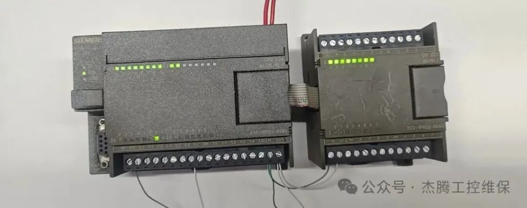 PLC
PLC
PLC is a computer specifically designed for industrial environments. Unlike the computers we use daily, which have keyboards, mice, and monitors, PLCs control machines or entire production lines through programming.
Once a PLC is damaged during use, it can be very troublesome. However, if you are aware of the common faults that occur with PLCs, troubleshooting becomes much easier:
-
Communication failure
-
Input without output at a certain point
-
Power indicator light not lit
By checking these areas, you can usually resolve the issue. Repairing a PLC can be very challenging, especially in cases of main unit damage. Therefore, if you need to repair a PLC, be sure to clearly communicate the fault to the technician! Common PLCs on the market include Siemens, Mitsubishi, and Omron.
Understanding these devices is not difficult; the key is to grasp their roles at different levels:
-
Decision Level: PLC is responsible for logical judgment and overall coordination
-
Control Level: Servo drives/inverters are responsible for executing commands accurately
-
Execution Level: Motors are responsible for the final action output
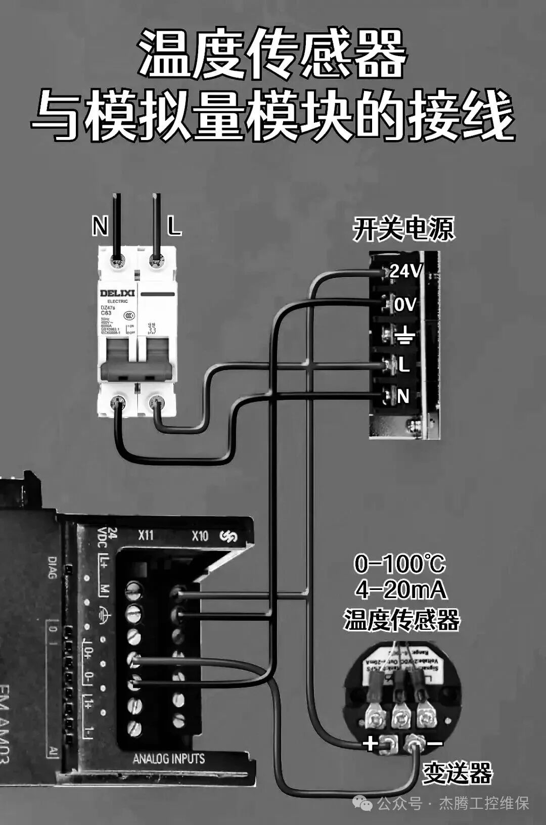
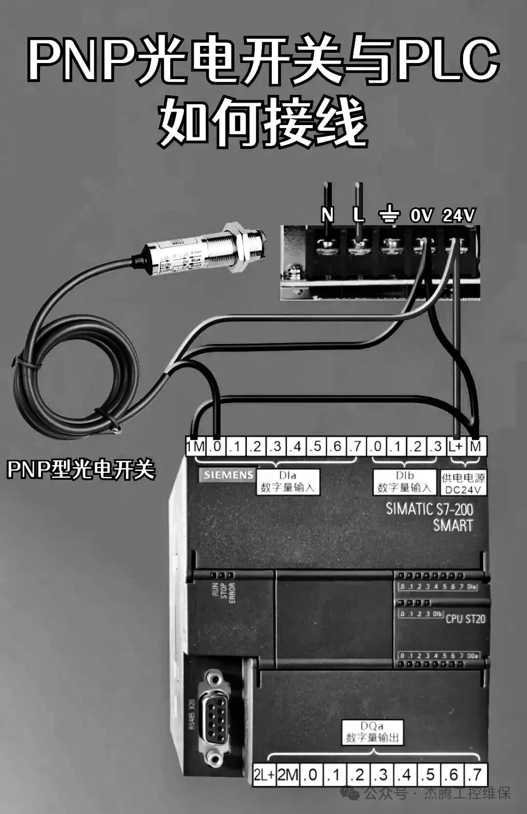
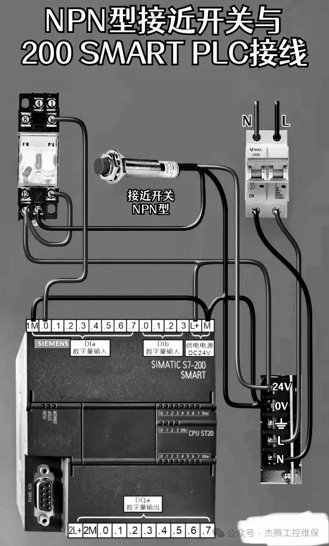
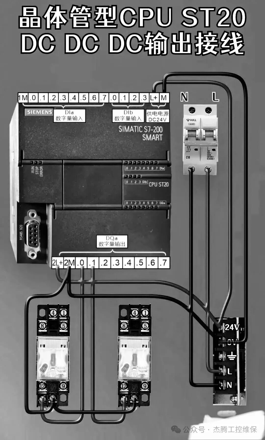
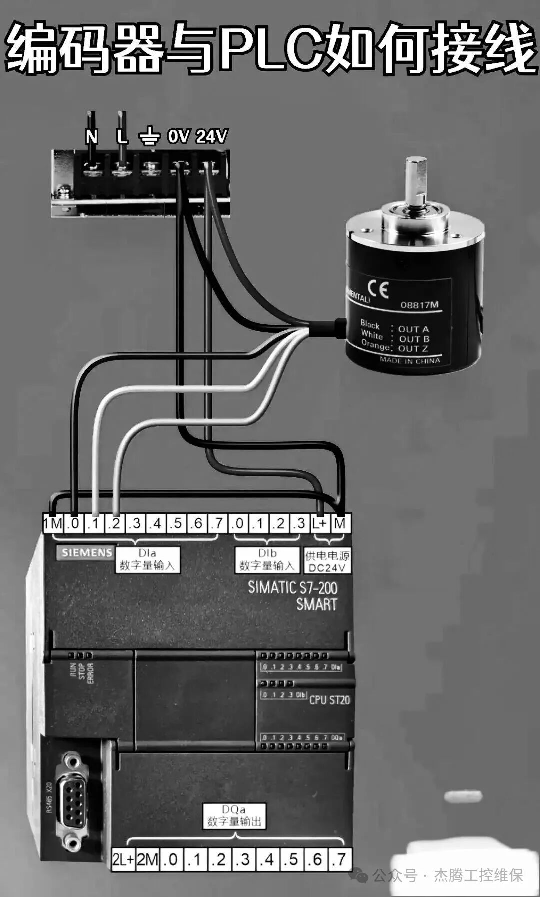
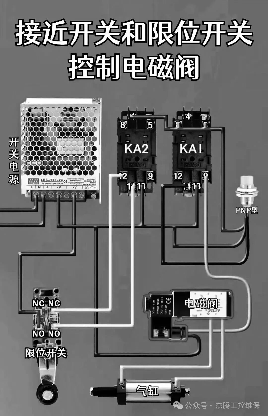
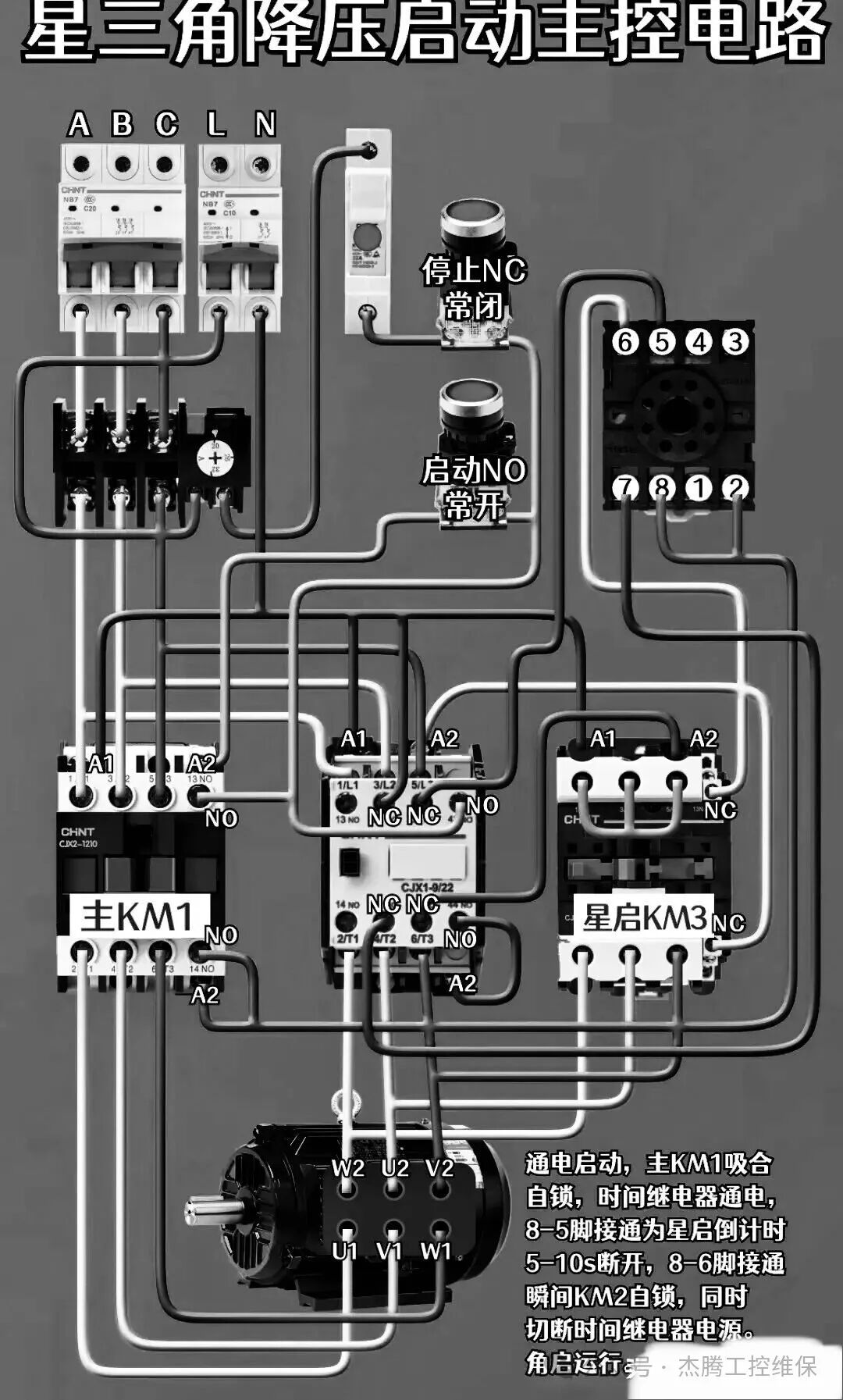
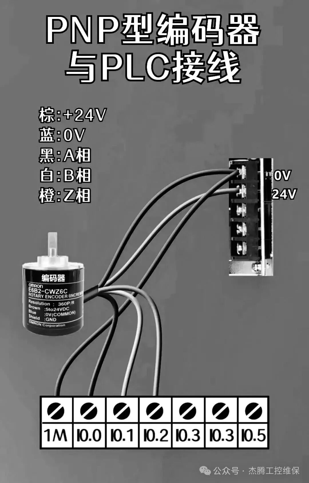
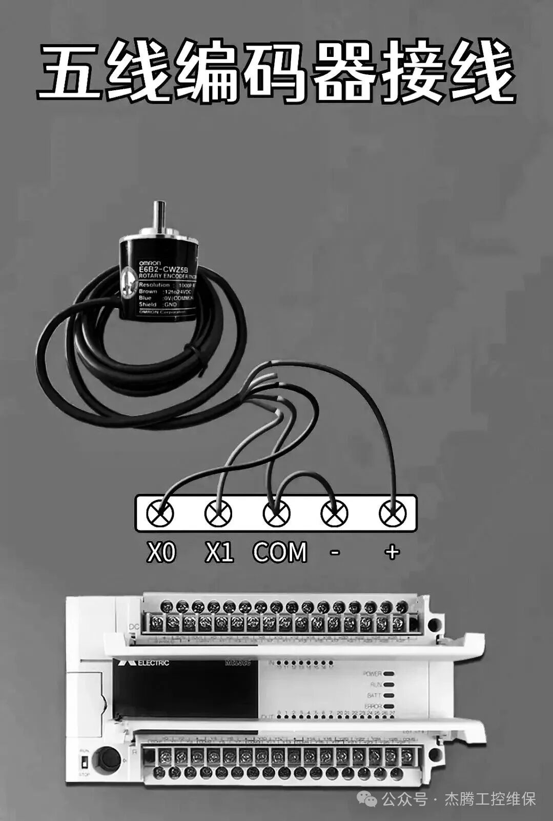
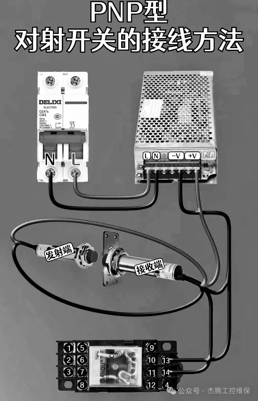
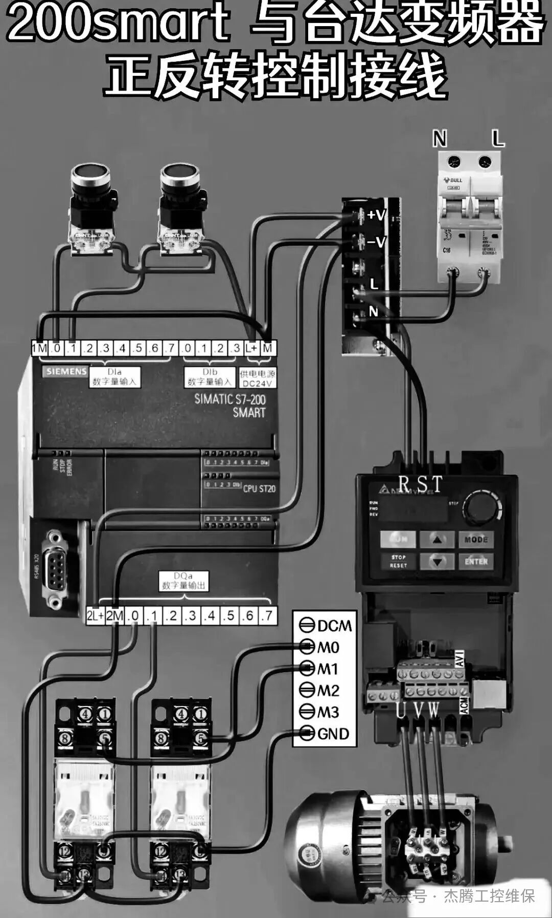
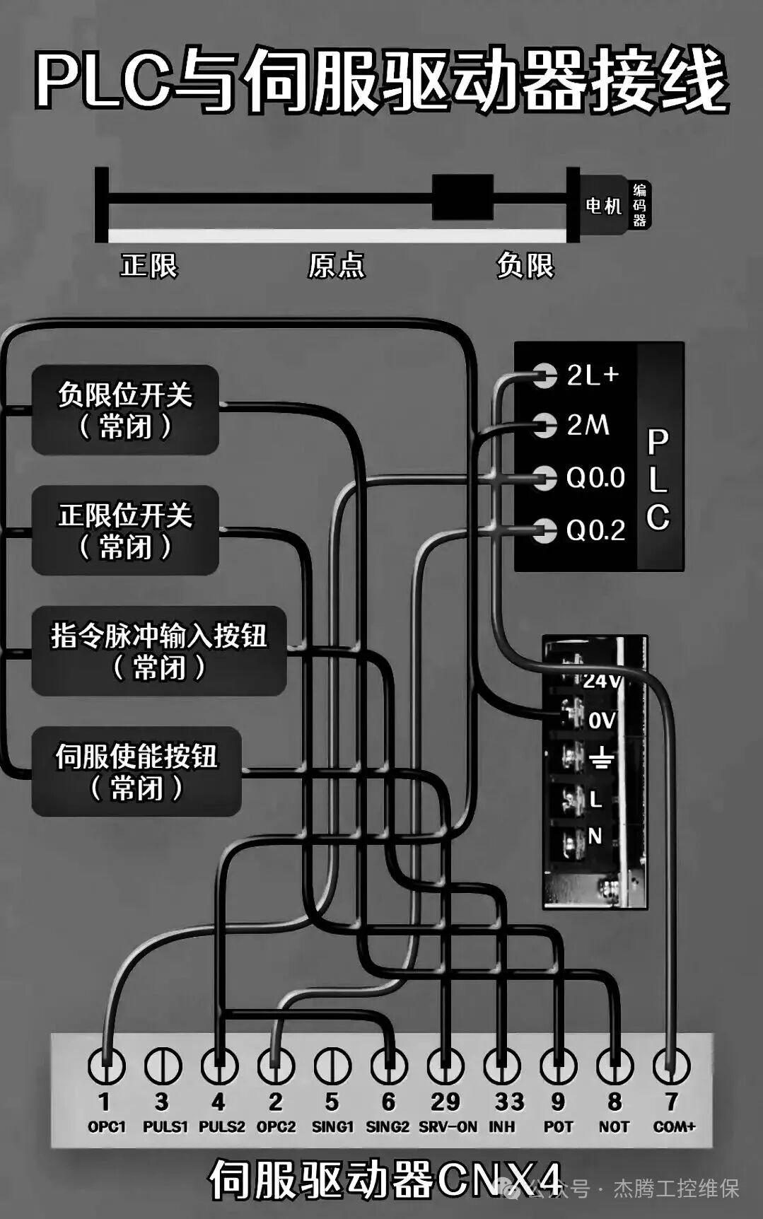
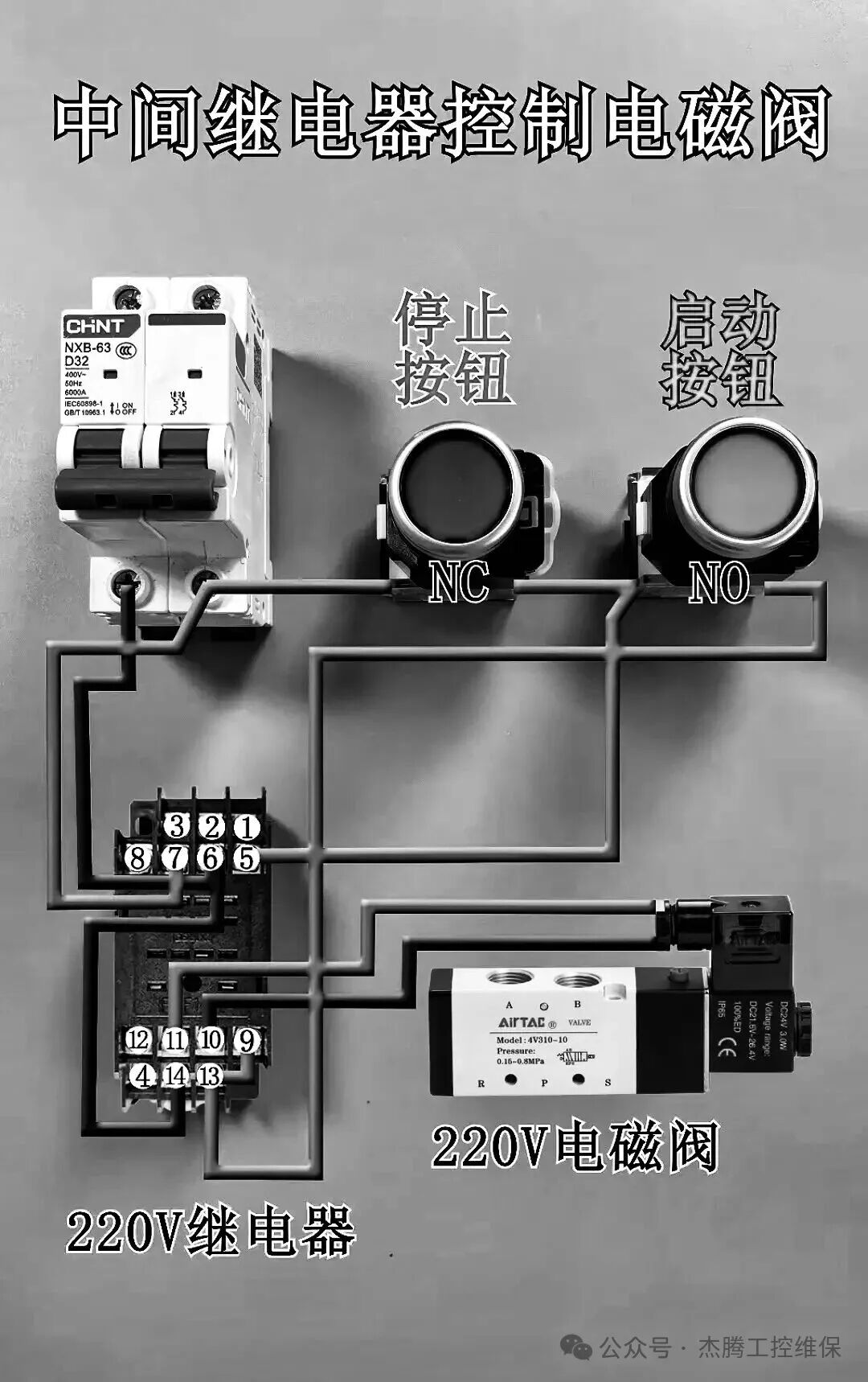
Now, let’s look at various wiring diagrams:

 The usual safety reminders must not be overlooked:1. Personnel without an electrician’s license are prohibited from operating: Installation, debugging, and maintenance of electrical equipment must be performed by certified professional electricians; unauthorized personnel are strictly prohibited from operating.
2. Power off before operation: Before any wiring or inspection, ensure that the equipment is completely powered off and hang a “Do Not Energize” warning sign.
3. Emergency stop function: Ensure that all equipment’s emergency stop buttons are functioning properly, are clearly positioned, and easy to operate.