 Search on WeChat
 Automation Knowledge Base
Hello everyone, today I want to talk about a practical problem I recently solved—how to control communication between the S7-1200 PLC and the V90 servo.
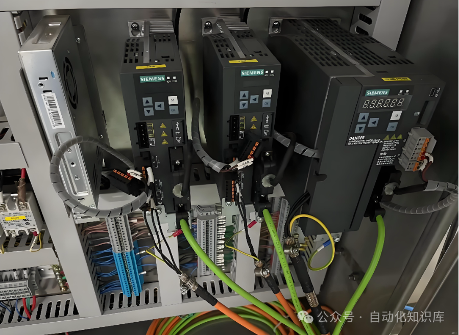
I remember when I first started, I spent several days flipping through the manual, feeling overwhelmed by the technical jargon. After some trial and error, I finally figured it out. I believe many of my friends in automation have encountered similar situations, so today I will share this practical experience in simple terms so that beginners can follow along.
📌 Why do we need communication control?
Those who have worked in a workshop know that PLC control of servos is a common operation—such as positioning conveyor belts on assembly lines and precise machining of machine tools, which rely heavily on this “partnership”.
When I first entered the industry, most workshops used hardwired control, with numerous tangled wires. Troubleshooting took a long time, and sometimes if the wires were connected incorrectly, I had to disassemble and reconnect them, which was particularly time-consuming.
Now, things are different; communication control is becoming increasingly popular. Last time, I helped a workshop change the control method of a production line, replacing hard wiring with communication. Not only did it reduce wiring by more than half, but I also didn’t have to climb up to adjust knobs during debugging; I could set parameters directly in the PLC, significantly improving efficiency. This is why I want to explain this knowledge point today—it can really save everyone a lot of trouble!
🔧 Core Configuration: Get These 5 Steps Right, and You’re Halfway There
When controlling the V90 servo, message selection is crucial. I have tried message 3 and standard message 111; message 3 requires using program blocks like MC_POWER, which can be a bit confusing for beginners;standard message 111 can directly use the FB284 “SINA_POS” function block, which can handle absolute positioning, homing, and jogging, making it more straightforward. Today, I will focus on the FB284 solution that I commonly use.
Before calling the function block, you need to set up the “connection bridge” between the PLC and the servo. These 5 steps are fundamental, and none can be skipped. I always check them against a checklist:
① 📥 First, install the “translation software”—add the GSD file
This step is like installing a translation tool before communicating with a foreigner. The GSD file is the “translation manual” for the PLC and V90 servo; without it, they cannot communicate. I usually download the latest version from Siemens’ official website, and after downloading, I import it directly into the TIA Portal software. Once imported successfully, I can find the V90 model in the hardware configuration.
② 🔢 Assign an “address” to the PLC—set the IP address
The PLC is like a workstation in the workshop; it needs a fixed IP address for the servo to locate it accurately. I typically set the PLC’s IP to 192.168.0.1 (you can adjust it according to the workshop’s subnet). When setting it, make sure it is in the same subnet as the servo’s IP; otherwise, it would be like two workstations on different floors, unable to connect.
③ 🏷️ Register the servo—set the IP and device name
The servo also needs its own IP and device name, and the device name must match exactly with what is set on the driver; even one letter off will cause issues. Last time, I spent half an hour debugging because I missed an underscore in the device name. I usually set the IP address to 192.168.0.2, corresponding to the PLC’s IP, which is also easy to remember.
④ 🤝 Establish a connection between the two
After adding both the PLC and V90 in the hardware configuration, you can connect them with an Ethernet cable. Once connected, click “Online Diagnostics” in TIA Portal. If you see the servo’s status as “Connected”, it means they are communicating; if it shows disconnected, check if the cable is securely plugged in and if the IP addresses are in the same subnet.
⑤ 📤 Agree on a “communication method”—add the message
This step is crucial; the PLC and servo must agree on how to exchange information. We use standard message 111, so when adding the message in the PLC’s hardware configuration, make sure to select 111 and ensure it matches the message set on the servo driver. I always double-check on the driver after setting to avoid control failure due to message mismatch.
⚙️ Key Point: How to Use the SINA_POS Function Block?
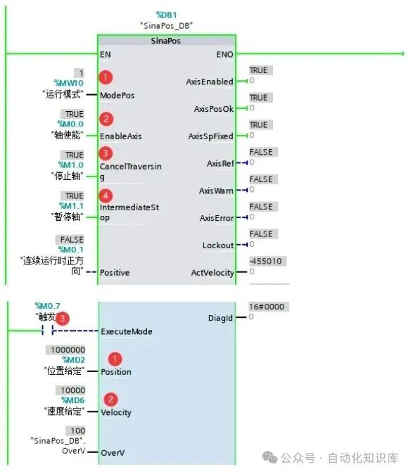
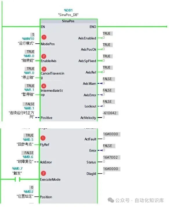
Once the previous configurations are done, it’s time for the core “SINA_POS” function block to take the stage. Figure 1 shows what this function block looks like; despite its many pins, the core function is to switch between different control modes by changing the value of the “ModePOS” pin—just like changing channels with a remote control, pressing different buttons achieves different functions. Figure 2 clearly indicates the pins corresponding to different modes for your reference.
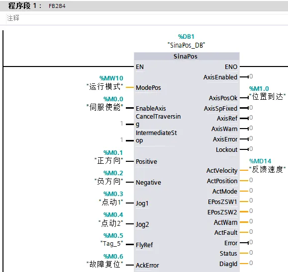
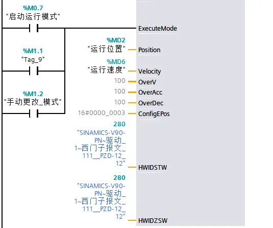
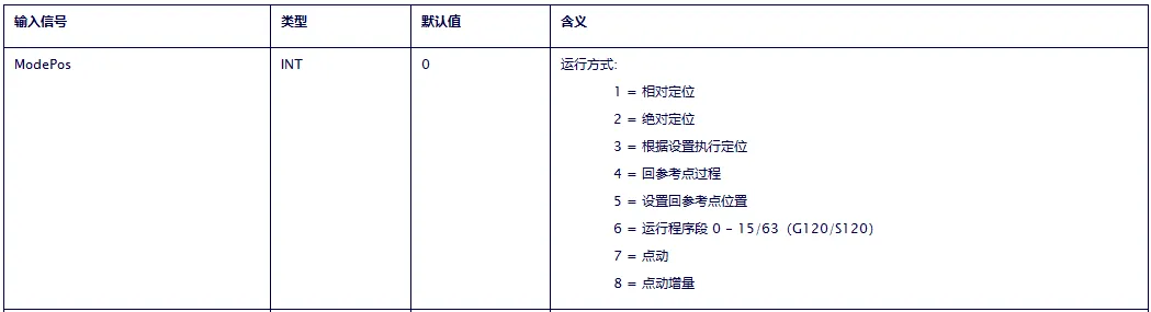
Next, I will explain several commonly used modes, combining my experience from debugging a conveyor belt, with practical details for each step:
① 📏 Mode 1: Relative Positioning—Specify “how many steps”
Relative positioning means moving the servo a specified distance, for example, moving the conveyor belt forward by 500 millimeters. The operation is simple: first set “ModePOS” to 1 (i.e., MW10 equals 1), then enable the axis, set the “position setpoint” (e.g., 500) and “speed setpoint” (e.g., 1000), and finally activate the “trigger” pin, and the servo will move according to the set parameters. During my last debugging session, I initially set the speed too low, causing the conveyor belt to move very slowly; after increasing the speed, it worked normally, so you can adjust it based on actual needs.
② 🎯 Mode 2: Absolute Positioning—Specify “which point to go to”
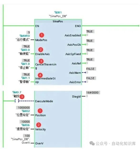
Absolute positioning means moving the servo to a fixed position, such as stopping the conveyor belt at the third workstation. Note that before absolute positioning, the servo must return to the reference point; otherwise, it won’t know where the “zero point” is and cannot accurately find the target position. I usually switch to mode 5 first, set the current position as the zero point, and after confirming the zero point is set correctly, I change “ModePOS” to 2, set the target position, and after triggering, the servo will move precisely to that location. Last time I used this mode to debug a sorting mechanism, achieving a positioning error of less than 1 millimeter, which was excellent.
③ 🔄 Mode 3: Continuous Operation—Keep “running”
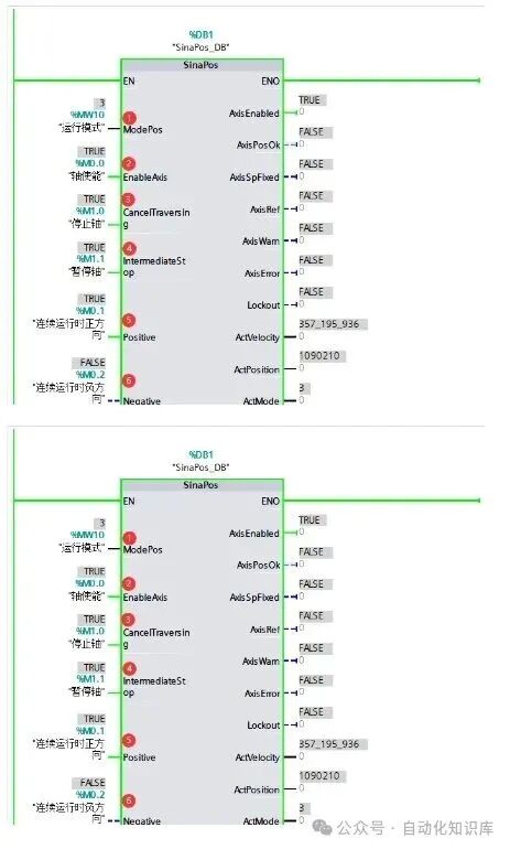
This mode is suitable for scenarios requiring continuous operation, such as a conveyor belt continuously transporting materials. Last time, when I debugged in a food workshop, I used this mode to keep the conveyor belt running; I just needed to set the speed, and after triggering, the servo would rotate at a constant speed until it received a stop signal. It is important to ensure safety measures are in place during continuous operation to avoid accidents.
④ 🏁 Mode 4: Return to Reference Point—Find the “starting point”
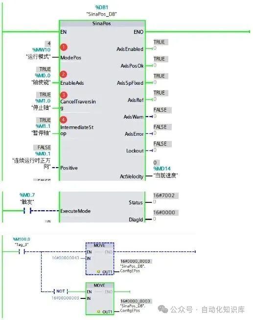
Returning to the reference point is a prerequisite for many controls, and mode 4 does just that. A key detail here is that during the return to zero process, M0.7 must remain 1. I usually associate an external button with this pin; when the button is pressed, it maintains a connected state. You can input the value 16#00000043 and replace M100.0 with the actual input point on the PLC. Last time during debugging, a faulty button connection caused the return to zero to fail, but after replacing it, everything worked fine, so ensure the reliability of the hardware.
⑤ 📍 Mode 5: Set Reference Point—Customize the “starting point”
Sometimes we don’t need to return to the servo’s default zero point but want to set a specific position as the reference point; in this case, we use mode 5. For example, during my last debugging session, I needed to set the initial position of the conveyor belt as the reference point. After switching to mode 5, the servo would record the current position as the zero point, and subsequent positioning would be based on this point, which is very convenient.
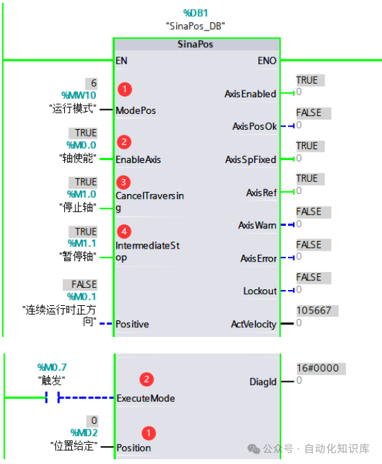
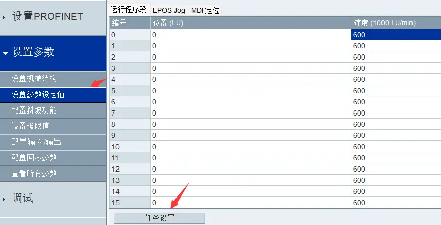
⑥ 📜 Mode 6: Run Program Segment—Follow the preset “process”
If the servo driver has preset some running parameters, mode 6 can directly call these program segments to run. For example, I previously set a “convey-stop-return” process in the driver; after switching to mode 6, the servo would run according to this preset process without needing to write complex programs in the PLC, saving a lot of effort.
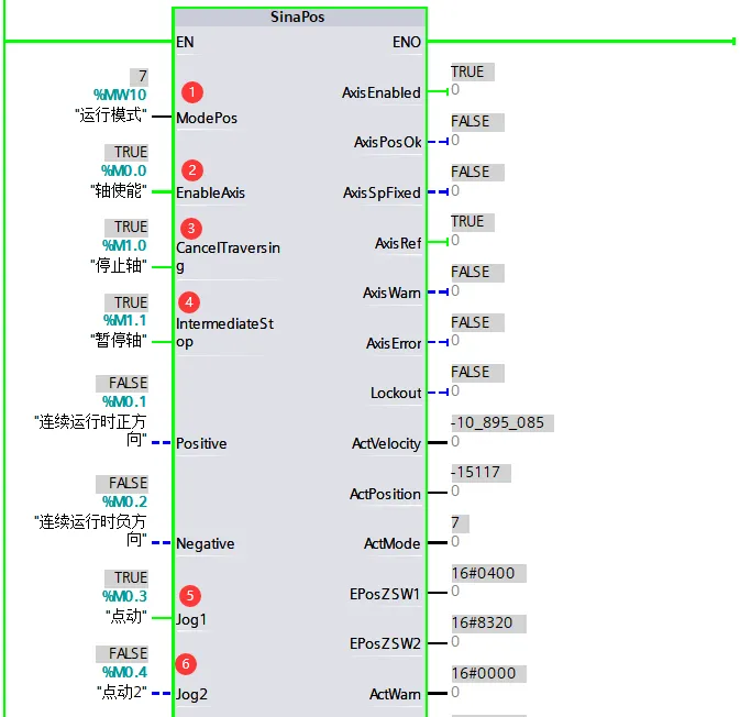
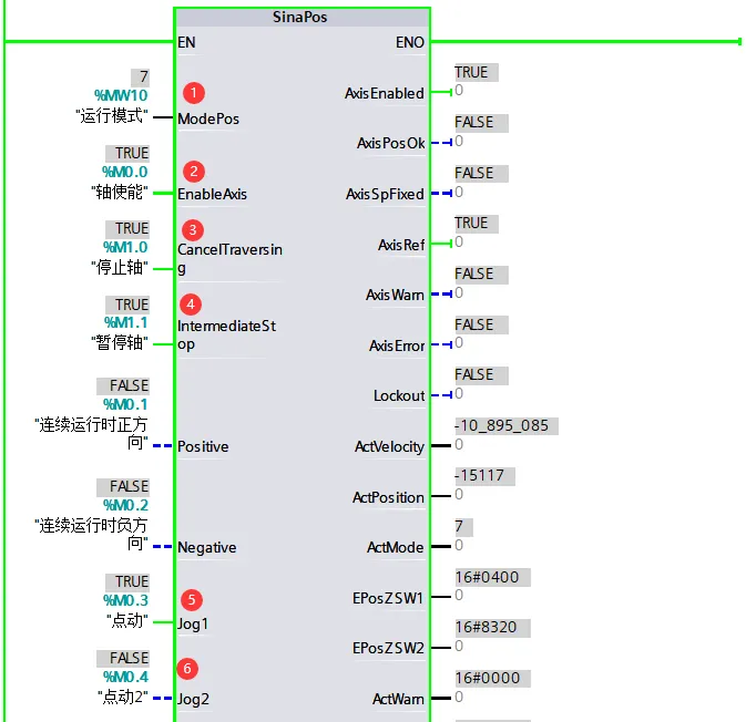
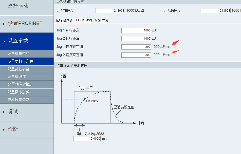
⑦ 🖱️ Mode 7: Jogging—”Move a little bit”
The jogging mode is very useful during debugging; for example, if we want to fine-tune the servo’s position, we can use mode 7. After triggering jogging, the servo will move slowly, and releasing the trigger signal will stop it, just like dragging an icon with a mouse, allowing for precise adjustments to the desired position. I always use jogging mode to calibrate positions when installing new devices, which is particularly practical.
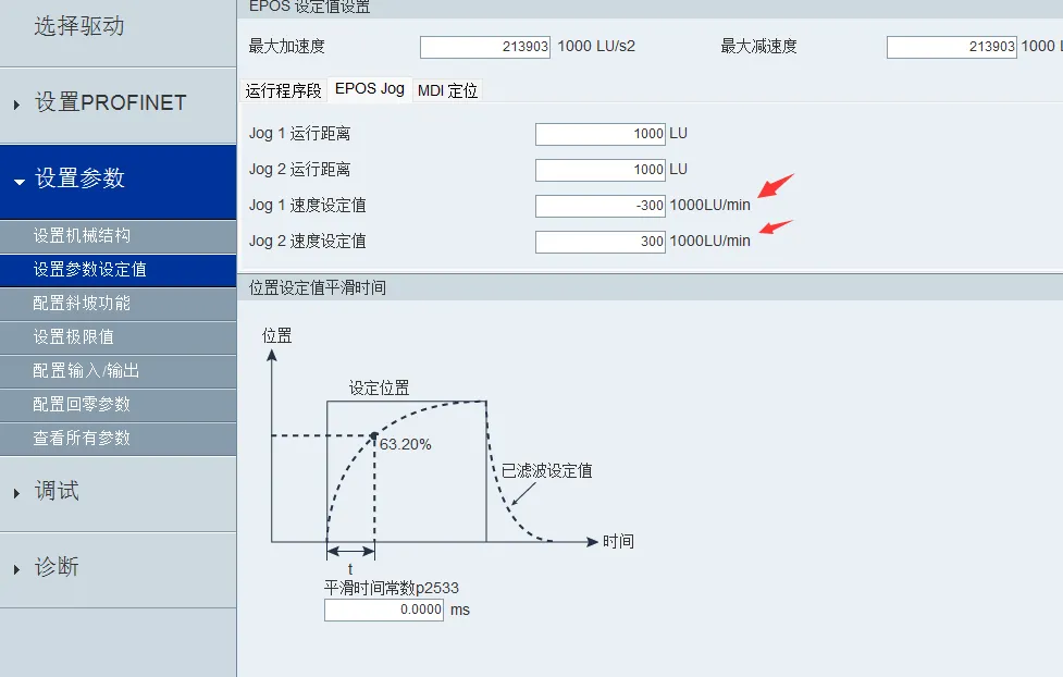
⑧ 🔍 Mode 8: Incremental Jogging—”Move step by step”
Mode 8 is incremental jogging, and the difference from mode 7 is that mode 7 moves continuously, while mode 8 moves a fixed incremental value each time it is triggered. For example, if I set the increment to 10 millimeters, each time I trigger jogging, the servo will move 10 millimeters and then stop. This mode is suitable for scenarios requiring precise step-by-step movement, such as step positioning on an assembly line.
💡 A Few Final Thoughts
In fact, communication control between the S7-1200 PLC and the V90 servo may seem complex, but once you break down the steps and take them one at a time, it is not difficult. When I first started learning, I also encountered many pitfalls, such as incorrect IP addresses, message mismatches, and poor button connections, but each time I solved a problem, I gained significant insights.
When you are practicing, be patient, check each step carefully, and if you encounter problems, don’t panic; start troubleshooting from the hardware connections and parameter settings. If you encounter specific issues during debugging, feel free to leave a comment, and we can discuss solutions together!
If you find this article useful, don’t forget to give it a “thumbs up” and share it with friends in automation!
Previous Recommendations
PLC Control of Stepper Drivers Made Simple! (Includes Practical Wiring Diagrams)
Electrical Experts Share: 12 PLC Programming Tips to Save Beginners 3 Years of Trouble
PLC Engineers’ Secret Tips: View Code Flow Directly on HMI, No Need to Panic When Equipment Stops!
Electrical Workers’ Complete Wiring Diagrams for Meters! No More Fear of “Looks Easy, Connects Wrong”
Electrical Workers’ Complete Cable Code Guide! 90% of Peers Have Saved It
Analog Conversion Techniques Used by Electricians, Easy for Beginners to Master!
Must-Read for Beginners! Practical Guide to Drawing Circles with S7-200SMART, Free Complete Program Available
Siemens S7-1200 PLC Programming: Practical Guide to Parameterized FC Blocks, Understandable for Beginners!
How to Write Practical PLC Alarm Programs? Save This Practical Experience for Beginners!
No Need to Go to the Workshop! 1:1 Virtual Simulation Platform, Practice PLC Debugging at Home
Share Collect
 View
View LikeFollowSo You Can Find Me Next Time