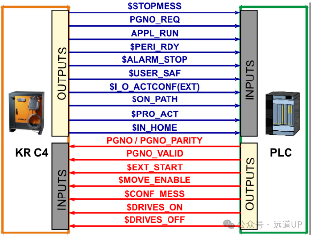
Before the external startup of KUKA robots, the configuration on the robot side has been introduced. For complete operation, the PLC side also requires a complete configuration.1. The PLC configuration mainly controls the timing of interaction signals with the robot. There are many specific timing introductions, so we will directly introduce the finished program. The program has undergone preliminary testing and can start and stop normally. This program has only one main program and does not require switching. If multiple program switching is needed, adjustments to the program number related programs are required.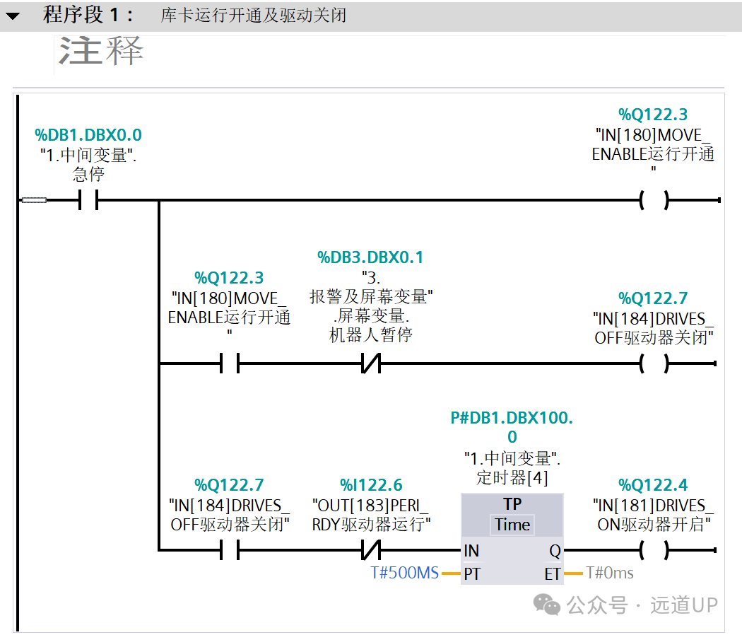
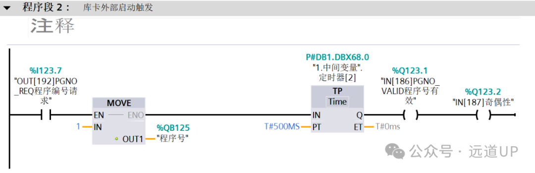
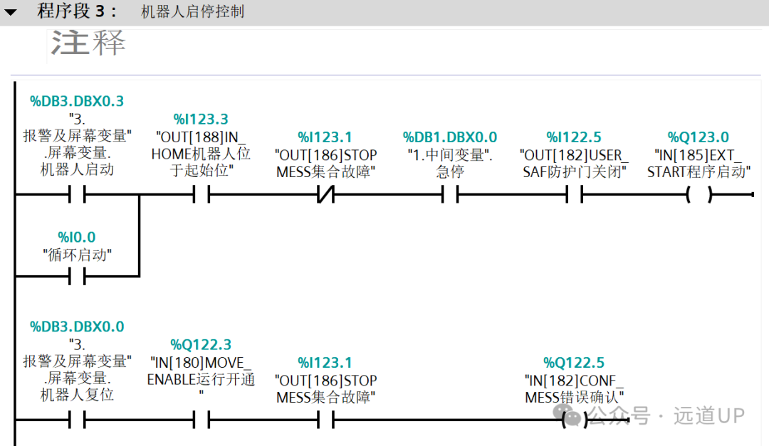
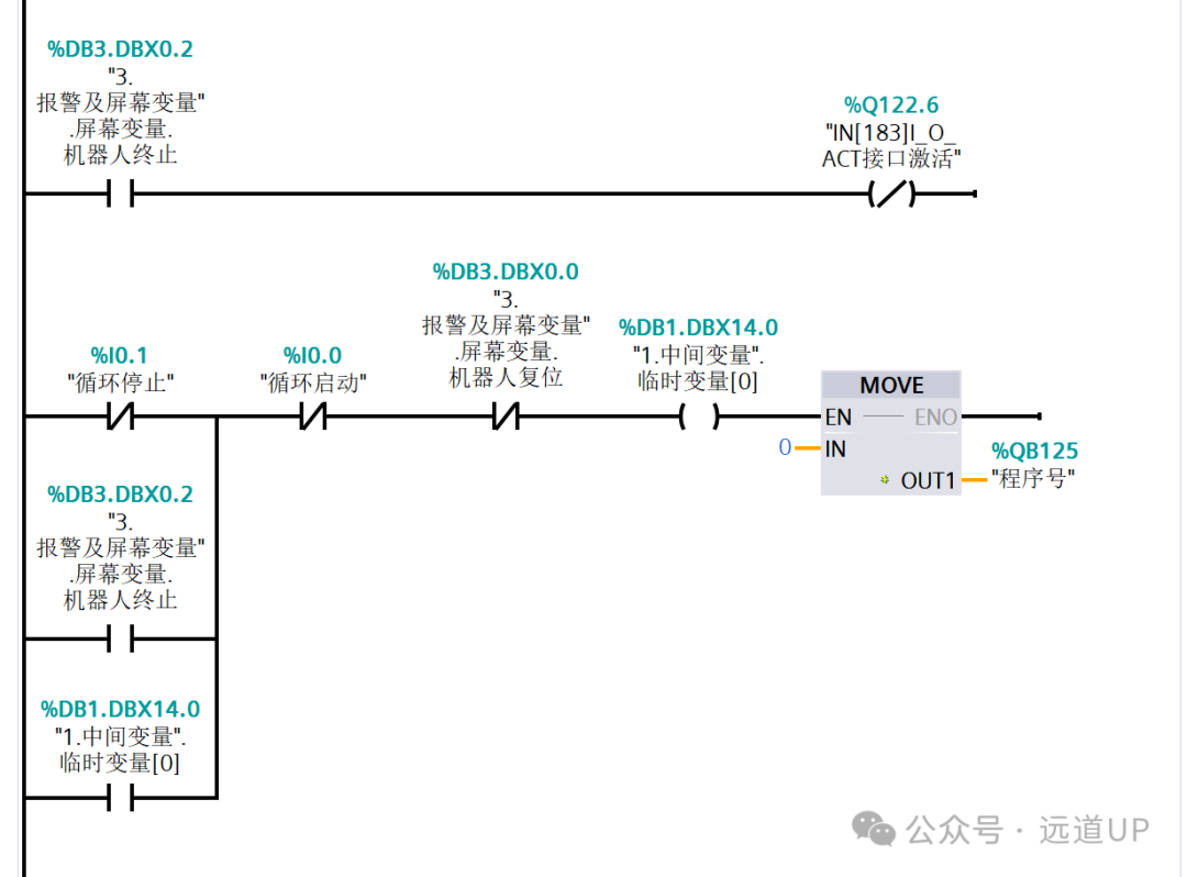 The following is a detailed introduction to the external operation signals and timing:2. After ensuring safety, the PLC confirms the power-on signal.
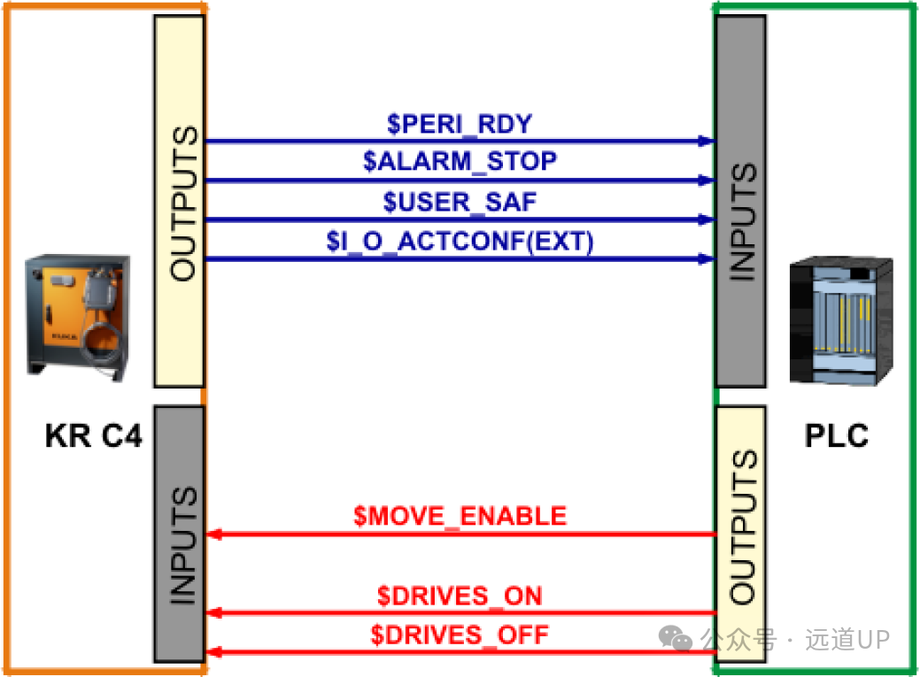 OUTPUTS:
1. $PERI_RDY – The drive device is in standby mode
This output indicates to the superior control system that the drive device has been activated through the robot control system.
2. $PERI_RDY – Once feedback from the drive device is received, the signal $DRIVES_ON will be withdrawn.
3. $USER_SAF – Operator protection device / safety door
This output resets when the protection inquiry switch (operating mode AUT) is opened or the confirmation switch (operating mode T1 or T2) is released.
4. $ALARM_STOP – Emergency stop
This output resets in the event of the following emergency stop situations: the emergency stop button on the KUKA control panel (KCP) is pressed, internal emergency shutdown, and external emergency stop.
5. $I_O_ACTCONF – External automatic operation activation
When the external automatic operation mode is selected and the input $I_O_ACT is TRUE (generally set to $IN[1025]), the output will be TRUE.
INPUTS:
1. $MOVE_ENABLE – Allow operation
This input is used by the superior controller to check the robot drive. TRUE allows manual operation and program execution, while FALSE stops all drive devices and locks all active commands to connect the drive device.
2. $DRIVES_ON – Drive device activated
If a high pulse is applied to this input for at least 20 milliseconds, the superior control system will activate the robot drive device.
3. $DRIVES_OFF – Drive device deactivated
If a low pulse is applied to this input for at least 20 milliseconds, the superior control system will deactivate the robot drive device.
Prerequisites:
$USER_SAF – Safety door is closed
$ALARM_STOP – No emergency stop
$I_O_ACTCONF – External automatic operation activation
$MOVE_ENABLE – Allow operation
$DRIVER_OFF – Drive device deactivated
Process control: When prerequisites are met, activate $DRIVER_ON to connect the drive device, and the drive device will be in standby mode.
3. Signal confirmation
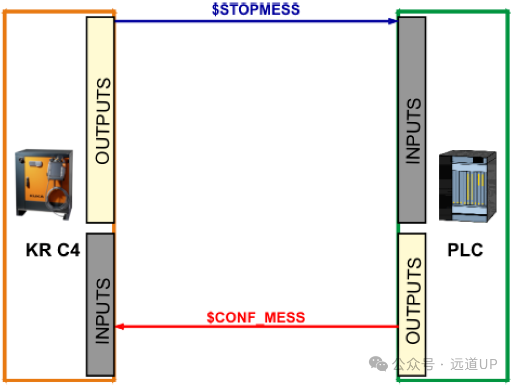
OUTPUTS:
1. $STOPMESS – Stop message
This output is set by the robot control system to display a message to the superior controller indicating that a request to stop the robot has occurred (e.g., emergency stop button, operation enabled, or operator protection device).
INPUTS:
1. $CONF_MESS – Confirmation message
By assigning a value to this input, the superior controller will confirm the fault information after the cause of the fault has been eliminated.
4. Start program CELL.SRC
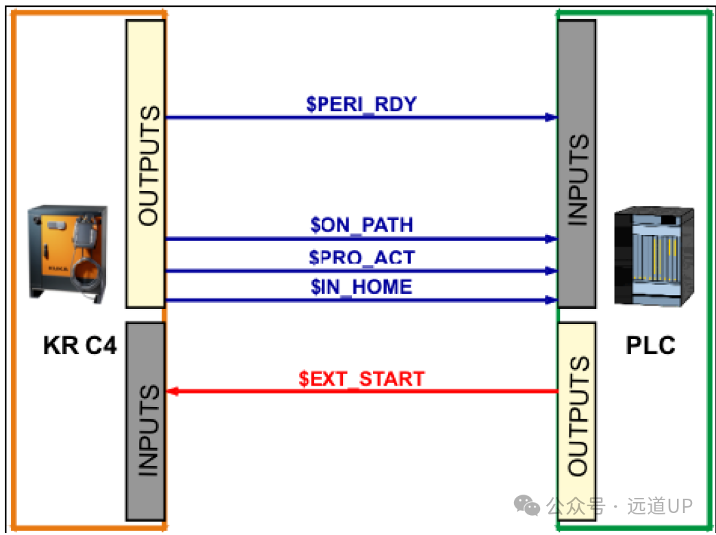
OUTPUTS:
1. $PERI_RDY – The drive device is in standby mode
2. $ON_PATH – The robot is on the trajectory
As long as the robot is on the programmed trajectory, this output will be assigned. After performing BCO operation, the output ON_PATH will be assigned. The output remains active until the robot leaves the trajectory, the program is reset, or a statement is selected. However, the signal ON_PATH has no tolerance range; once the robot leaves the trajectory, this signal will reset.
3. $PRO_ACT – Program activated / running
When a process at the robot level is activated, this output is always assigned. During program processing or interruption, the process is in an activated state. The program processing at the end of the program is only considered deactivated after all pulse outputs and triggers have been processed. In the event of a fault stop, the following situations can be distinguished:
1) When the interruption has been activated but has not been edited at the time of the fault stop, the process is considered deactivated. ($PRO_ACT=FALSE).
2) When the interruption has been activated and has been edited at the time of the fault stop, the process is considered activated ($PRO_ACT=TRUE) until the interruption program is processed or runs to HALT ($PRO_ACT=FALSE).
3) When the interruption has been activated and the program runs to HALT, the process is considered deactivated ($PRO_ACT=FALSE).
4) When the interruption condition is met at a certain moment, the process is considered activated ($PRO_ACT=TRUE) until the interruption program is processed or runs to HALT ($PRO_ACT=FALSE).
4. $IN_HOME – The robot is at the home position
This output notifies the superior controller that the robot is at its home position.
INPUTS:
1. $EXT_START – External start
When this input is set, the input/output interface will start or continue a program (generally CELL.SRC) when activated.
Prerequisites
$PERI_RDY – The drive device is in standby mode
$IN_HOME – The robot is at the home position
No $STOPMESS – No stop message
External start
$EXT_START – Activate external start (positive edge pulse)
The CELL program is running
$PRO_ACT – Report that the CELL program is running
$ON_PATH – Once feedback is received that the robot is on the trajectory, the signal $EXT_START will be withdrawn.
Process control: After meeting the prerequisites, activate the external start to enter CELL operation.
5. Program number transmission and interaction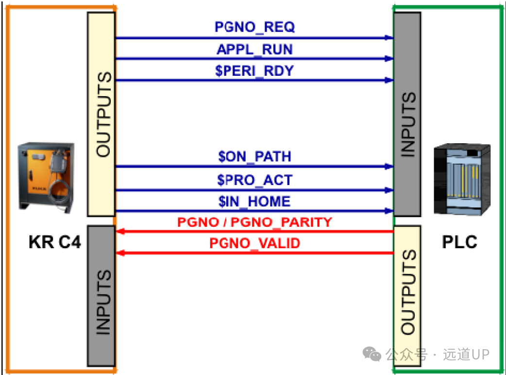
OUTPUTS:
1. PGNO_REQ – Program number inquiry
When the signal changes at this output, it requests the superior controller to transmit a program number. If PGNO_TYPE value is 3, PGNO_REQ will not be analyzed.
2. APPL_RUN – Application program is running
The robot control system notifies the superior control system that the robot is processing the relevant program by setting this output.
3. $PERI_RDY – The drive device is in standby mode
4. $ON_PATH – The robot is on the trajectory
5. $PRO_ACT – Program activated / running
6. $IN_HOME – The robot is at the home position
This output notifies the superior controller that the robot is at its home position.
INPUTS:
1. PGNO_PARITY – Program number parity
The input for the superior control system to transmit the parity of the program number. Parity is used to identify errors in the transmitted information word. Here, the information word is a sequence of bits. “Parity” indicates the number of bits occupied by 1 in the information word; if the number of bits is even, it is called even parity (“even” in English), otherwise it is odd parity (“odd” in English). The parity code adds a parity bit to the information word, also known as the Parity bit. The method is to ensure that all code words to be transmitted have the same parity. Depending on whether even or odd parity is to be transmitted, the suffix is E or O, corresponding to the examples shown in the figure. The parity result, which is one bit longer than the information word, is called the code word. The method of using parity bits to identify errors is called parity checking. Since it is unknown where the error occurs in the code word, it cannot correct the error. Additionally, for a single parity bit (N = 1), only an odd number of parity bit errors can be determined in a code word. An even number of parity bit errors cannot be determined because, in this case, the parity remains unchanged in the code word.
PGNO_VALID – Program number valid
The input for the superior control system to transmit the read program number command.
Program number transmission and confirmation of program number transmission (correct data type (PGNO_TYPE), program number length (PGNO_LENGTH), and the first bit of the program number (PGNO_FBIT) have been set)
Process control:
Under the condition of meeting the prerequisites, program number transmission and confirmation will be performed, and then the corresponding program will be selected for operation.
Prerequisites
$PERI_RDY – The drive device is in standby mode
$PRO_ACT – The CELL program is running
$ON_PATH – The robot is on the trajectory
$IN_HOME – The robot is at the home position (HOME), no need to restart
PGNO_REQ – There is a program number request
Program number transmission and confirmation
Program number transmission (correct data type (PGNO_TYPE), program number length (PGNO_LENGTH), and the first bit of the program number (PGNO_FBIT) have been set) PGNO_VALID – Switch the program number to valid (confirmation, positive edge)
2. APPL_RUN – Report that the application program is running
The robot leaves the home position (HOME), and after the application program ends, the robot returns to the home position (HOME).