
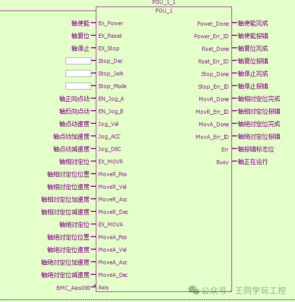
XINJE Bus Servo PLC Function Block (POU_1_1) Packaging Diagram, which illustrates the typical interface structure of this packaging in motion control. This packaging is commonly used to integrate XINJE servo drives (such as through bus protocols like EtherCAT, CANopen, etc.) with PLCs (for example, XINJE XC series PLCs) to achieve precise control of axes.
 If you need to communicate and learn, you can scan the QR code to add WeChat Please add “discussion group” to learn industrial control knowledge together The program is at the bottom of the article Unique contact: 15325623428 (same number for WeChat)
1. Main Application Scenarios of XINJE Bus Servo Packaging
-
Automated Production Lines
- Used in devices requiring high precision positioning and synchronous control, such as packaging machines, labeling machines, and sorting machines.
- Multi-axis linkage (e.g., X/Y/Z axis coordination) to achieve complex trajectory motion.
Robotic Arms and Robot Systems
- As the control unit for joint motors, in conjunction with PLCs to achieve multi-axis coordinated actions.
- Supports switching between various modes such as position, speed, and torque.
CNC Machine Tools and Processing Centers
- Achieves high-speed, high-precision feed motion control.
- Supports interpolation, arc, and linear path planning.
Printing and Cutting Equipment
- In scenarios requiring precise positioning and high-speed response, such as laser cutting and screen printing.
2. Significance of XINJE Bus Servo Packaging
✅ 1. Simplifies Programming and Debugging
- Encapsulates complex servo communication protocols (such as EtherCAT) into standard function blocks (FB), allowing users to avoid understanding the underlying communication details.
- Provides clear input and output interfaces (such as
<span>EX_MOV_R</span>,<span>MoveR_Done</span>), facilitating configuration and debugging.
✅ 2. Improves System Stability and Reliability
- The encapsulation handles state feedback, error code parsing, timeout retries, etc., reducing the risk of misoperation.
- Automatically manages enable, reset, stop, and other logical processes to avoid faults caused by illegal commands.
✅ 3. Supports Multiple Motion Modes
| Function | Description |
|---|---|
Relative Positioning (<span>EX_MOV_R</span>) |
Moves a specified distance from the current position |
Absolute Positioning (<span>EX_MOV_A</span>) |
Moves to a specified absolute position |
Jog Control (<span>Jog</span>) |
Manually fine-tune the position, suitable for debugging |
| Acceleration/Deceleration Settings | Configurable acceleration and deceleration for smooth motion |
✅ 4. Strong Real-Time and Synchronization
- Bus-type servos (such as EtherCAT) have low latency and high synchronization, suitable for multi-axis linkage.
- Supports master-slave synchronization, electronic gear ratios, cam curves, and other advanced functions.
✅ 5. Easy to Expand and Maintain
- Modular design, one axis per function block, convenient for copying and modification.
- Clear error messages (such as
<span>Power_Err_ID</span>,<span>MovR_Err_ID</span>), facilitating quick diagnosis.
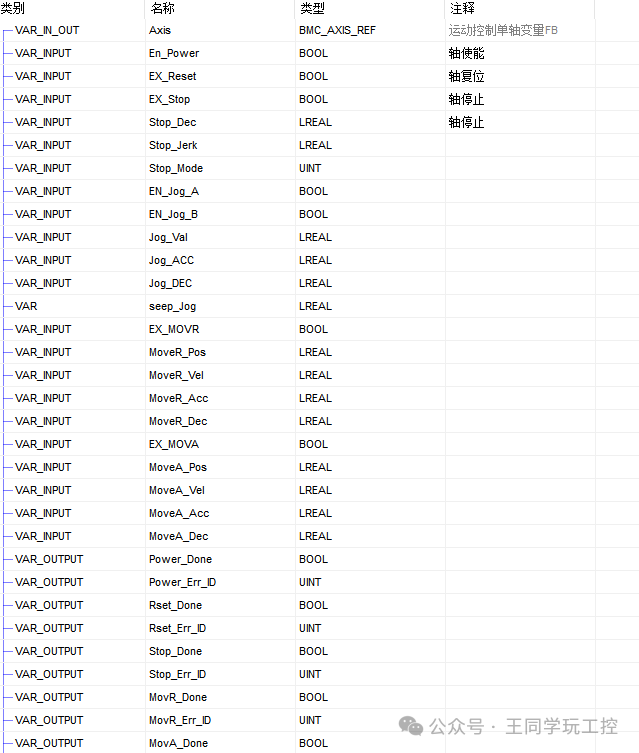
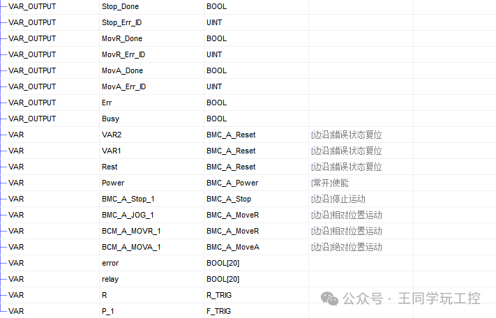
3. Key Parameter Descriptions in the Diagram (combined with your screenshots)
| Input Parameters | Usage |
|---|---|
<span>En_Power</span> |
Enable axis |
<span>EX_Reset</span> |
Axis reset command |
<span>EX_Stop</span> |
Stop axis operation |
<span>EN_Jog_A/B</span> |
Forward/Reverse jog enable |
<span>Jog_Val</span> |
Jog speed |
<span>Jog_ACC/DEC</span> |
Jog acceleration/deceleration |
<span>EX_MOV_R</span> |
Start relative positioning |
<span>MoveR_Pos/Vel/Acc/Dec</span> |
Target position, speed, acceleration, and deceleration for relative positioning |
<span>EX_MOV_A</span> |
Start absolute positioning |
<span>MoveA_Pos/Vel/Acc/Dec</span> |
Target parameters for absolute positioning |
<span>Axis</span> |
Specify the axis number to control (e.g., BMC_Axis000) |
| Output Parameters | Meaning |
|---|---|
<span>Power_Done</span> |
Enable successful |
<span>Power_Err_ID</span> |
Reason for enable failure |
<span>Rset_Done</span> |
Reset completed |
<span>Stop_Done</span> |
Stop completed |
<span>MovR_Done</span> |
Relative positioning completed |
<span>MovA_Done</span> |
Absolute positioning completed |
<span>Busy</span> |
Currently running |
<span>Err</span> |
Error flag |
4. Practical Usage Recommendations
- Set acceleration and deceleration parameters reasonably: Avoid excessive impact that affects lifespan.
- Enable alarm monitoring: Timely handle
<span>Err</span>and error codes. - Use with HMI: Can display current status, position, speed, and other information.
- Pay attention to synchronization time for multi-axis linkage: Especially when using interpolation or cams.
- Regularly calibrate the origin: Particularly after long-term operation, which may cause drift.
5. FB Block Packaging
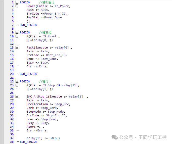
REGION //Axis Initialization
Power(Enable := En_Power,
Axis := Axis,
ErrCode =>Power_Err_ID ,
PwrStat =>Power_Done
);
END_REGION
REGION //Axis Reset
R(Clk := EX_Reset ,
Q =>relay[0] );
Rest(Execute := relay[0] ,
Axis := Axis,
ErrCode => Rset_Err_ID,
Done => Rset_Done,
Busy => Busy,
Err => Err);
END_REGION
REGION //Axis Stop
R(Clk := EX_Stop OR relay[11],
Q =>relay[1] );
BMC_A_Stop_1(Execute := relay[1] ,
Axis := Axis,
Deceleration := Stop_Dec,
Jerk := Stop_Jerk,
StopMode := Stop_Mode,
ErrCode => Stop_Err_ID,
Done => Stop_Done,
Busy => Busy,
Abort => ,
Err =>Err );
relay[11] := FALSE;
END_REGION
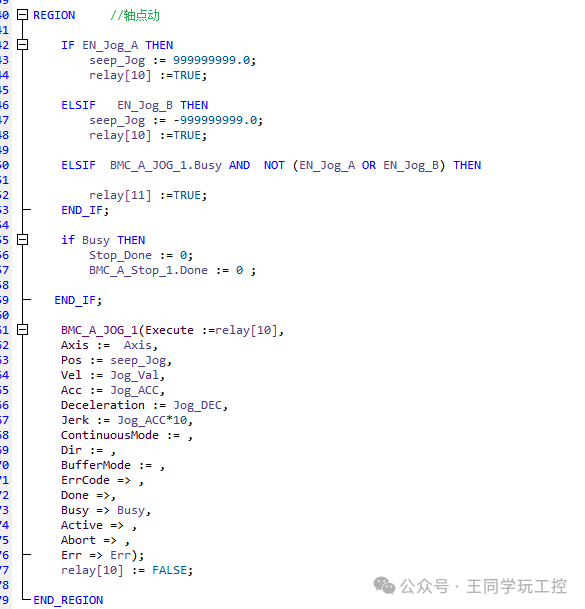
REGION //Axis Jog
IF EN_Jog_A THEN
seep_Jog := 999999999.0;
relay[10] :=TRUE;
ELSIF EN_Jog_B THEN
seep_Jog := -999999999.0;
relay[10] :=TRUE;
ELSIF BMC_A_JOG_1.Busy AND NOT (EN_Jog_A OR EN_Jog_B) THEN
relay[11] :=TRUE;
END_IF;
if Busy THEN
Stop_Done := 0;
BMC_A_Stop_1.Done := 0 ;
END_IF;
BMC_A_JOG_1(Execute :=relay[10],
Axis := Axis,
Pos := seep_Jog,
Vel := Jog_Val,
Acc := Jog_ACC,
Deceleration := Jog_DEC,
Jerk := Jog_ACC*10,
ContinuousMode := ,
Dir := ,
BufferMode := ,
ErrCode => ,
Done =>,
Busy => Busy,
Active => ,
Abort => ,
Err => Err);
relay[10] := FALSE;
END_REGION
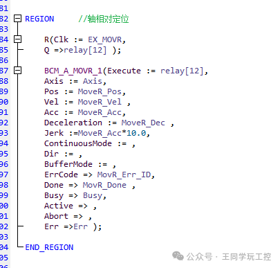
REGION //Axis Relative Positioning
R(Clk := EX_MOVR,
Q =>relay[12] );
BCM_A_MOVR_1(Execute := relay[12],
Axis := Axis,
Pos := MoveR_Pos,
Vel := MoveR_Vel ,
Acc := MoveR_Acc,
Deceleration := MoveR_Dec ,
Jerk :=MoveR_Acc*10.0,
ContinuousMode := ,
Dir := ,
BufferMode := ,
ErrCode => MovR_Err_ID,
Done => MovR_Done ,
Busy => Busy,
Active => ,
Abort => ,
Err =>Err );
END_REGION
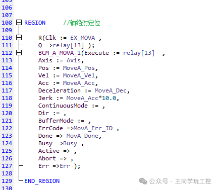
REGION //Axis Absolute Positioning
R(Clk := EX_MOVA ,
Q =>relay[13] );
BCM_A_MOVA_1(Execute := relay[13] ,
Axis := Axis,
Pos := MoveA_Pos,
Vel := MoveA_Vel,
Acc := MoveA_Acc,
Deceleration := MoveA_Dec,
Jerk := MoveA_Acc*10.0,
ContinuousMode := ,
Dir := ,
BufferMode := ,
ErrCode =>MovA_Err_ID ,
Done => MovA_Done,
Busy =>Busy ,
Active => ,
Abort => ,
Err =>Err );
END_REGION
 1. Siemens 1200 and 200 Smart – MODBUS-TCP Communication and Open TCP Communication2. Siemens Incremental PID Algorithm with Integral Separation3. Powder Material Ratio Quantitative Weighing System Design – S7-1200 + Filtering Algorithm4. XINJE PLC Axis Initialization FB Block, Filtering FB Block, Random Number FB Block5. V90 Servo Message 102 + Auxiliary Message 750 Torque Control – Siemens 1200 PLC – Pure Technical Sharing6. Grate Sewage Treatment Control System Design – Siemens 1200 (modbus communication, S7 communication) Dual PLC Communication – Pure Technical Sharing7. Time Password Lock – Siemens 1200 – SCL Language (FB Block Packaging) Complete Version – Pure Technical Sharing8. Vertical Packaging Machine Control System Design – Application of Electronic Cam – Chase Cut Flying Shear (Pure Technical Sharing)9. Custom Electronic Cam – Flying Shear (Rotary Cutting) – Pure Technical Sharing