PLC control has high starting efficiency, fast response, fewer connections, and convenient control, and PLC is widely used in industrial automation control. PLC has numerous instructions, and flexibly applying these instructions in programming is a crucial consideration for electrical control designers. This article uses the example of a three-phase asynchronous motor Y-△ automatic voltage reduction starting control to illustrate various methods of PLC programming. Keywords: PLC instructions ladder diagram Y-△ starting 1. Overview of PLC The programmable logic controller, abbreviated as PLC, is developed based on electrical control technology and computer technology, gradually evolving into a new type of industrial control device centered around microprocessors, integrating automation technology, computer technology, and communication technology. Currently, PLC is widely used in the automation control of various production machinery and processes, becoming one of the most popular and widely applied industrial control devices, recognized as one of the three pillars of modern industrial automation ( PLC, robotics, CAD/CAM). PLC not only fully utilizes the advantages of computers to meet the requirements of automatic control in various industrial production processes but also considers the technical level and habits of general electrical operators, using programming methods such as ladder diagrams or state transition diagrams, ensuring that the use of PLC remains accessible. When production processes need to change, programs can be modified on-site, making it convenient and flexible. In industrial automation control systems, the motor Y-△ voltage reduction starting is controlled by PLC. PLC control starting has advantages such as high efficiency, fast response, fewer connections, and convenient control. However, when designing PLC control circuits and programs, it is essential to consider the action characteristics of PLC and contactors; otherwise, theoretical analysis may not match actual operation, leading to issues such as failure to start and component damage. The following example illustrates the flexibility of PLC control using a three-phase asynchronous motor Y-△ automatic voltage reduction starting control. 2. Design Requirements When starting a three-phase asynchronous motor, the three-phase stator windings are connected in a star configuration to reduce the stator winding voltage, thereby decreasing the starting current. After starting, the three-phase stator windings are switched to a delta configuration for normal operation at rated voltage. Requirements: During starting, the three-phase asynchronous motor should be connected in Y type, and after a period, it should automatically switch to △ type operation. It is required that the Y type must be disconnected before the △ type can start to prevent short-circuiting the power supply due to the Y type not being disconnected. The automatic voltage reduction starting control circuit for the three-phase asynchronous motor is shown in the diagram below: 3. Design Solutions Solution 1: Use the control circuit diagram and ladder diagram corresponding to PLC control. By analyzing the action principles of the relay AC contact control circuit, determine the control objects and control content. The following steps are taken for PLC control:I/O allocation table and control functions 1. Circuit Design The wiring diagram and ladder diagram for PLC are shown in the diagram below:*2. Control Principles Press the start button SB1, the Y0 coil is energized and self-locks, Y1 is also energized, driving the contactor KM, KMY coils are energized, and the motor M is connected in a star configuration to start; the timer T0 is energized with a delay, after 10s the normally closed contact opens Y1, T0 normally open contact connects Y2, and the motor M switches from star to delta connection for full voltage operation. Pressing the normally closed stop button SB2, Y0, Y1, Y2 and T0 coils are all de-energized, stopping the motor. Solution 2: Use stack instructions MPS, MPD, MPP for PLC control. Stack instructions are used for multiple output circuits, providing convenience for programming. MPS instruction is used to store the calculation result at that instruction ( push onto the stack); MRD instruction is used to read the calculation result stored by MPS instruction ( pop from the stack); while MPP instruction is used to read and clear the calculation result stored by MPS instruction ( pop from the stack). It is important to note that MPS and MPP must be used in pairs. The ladder diagram for PLC is shown in the diagram below:

3. Design Solutions Solution 1: Use the control circuit diagram and ladder diagram corresponding to PLC control. By analyzing the action principles of the relay AC contact control circuit, determine the control objects and control content. The following steps are taken for PLC control:I/O allocation table and control functions
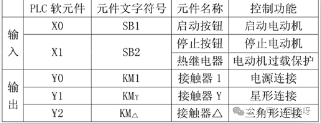
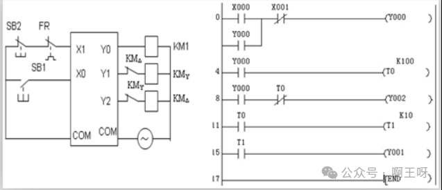
1. Circuit Design PLC wiring diagram and ladder diagram are shown in the diagram below:*2. Control Principles Press the start button SB1, Y0 coil is energized and self-locks, Y1 is also energized, driving the contactor KM, KMY coils are energized, and the motor M is connected in a star configuration to start; the timer T0 is energized with a delay, after 10s the normally closed contact opens Y1, T0 normally open contact connects Y2, and the motor M switches from star to delta connection for full voltage operation. Pressing the normally closed stop button SB2, Y0, Y1, Y2 and T0 coils are all de-energized, stopping the motor. Solution 2: Use stack instructions MPS, MPD, MPP for PLC control. Stack instructions are used for multiple output circuits, providing convenience for programming. MPS instruction is used to store the calculation result at that instruction ( push onto the stack); MRD instruction is used to read the calculation result stored by MPS instruction ( pop from the stack); while MPP instruction is used to read and clear the calculation result stored by MPS instruction ( pop from the stack). It is important to note that MPS and MPP must be used in pairs. The ladder diagram for PLC is shown in the diagram below:
Solution 3: Use transfer instructions for PLC control. The transfer instruction MOV function is to transfer source data to a specified target. When X0 is ON, the instruction executes, and PLC automatically converts the source data into binary; when X0 is OFF, the instruction does not execute, and the data remains unchanged. The ladder diagram for PLC is shown in the diagram below:
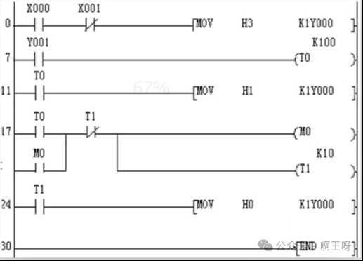
Control Principles: Press the start button SB1, the instruction executes, PLC first converts H3 automatically into binary 011, then transfers it to Y2~ Y0, so Y0, Y1 are energized, and the motor M is connected in a star configuration to start; the timer T0 is energized with a delay, after 10s it transfers 001 to Y2~ Y0, Y0 is energized, disconnecting Y1, after 1s T1 normally open contact connects Y2, and the motor M switches from star to delta connection for full voltage operation. Pressing the normally closed stop button SB2, Y0, Y1, Y2 and T0 coils are all de-energized, stopping the motor. Solution 4: Use alternating output instructions for PLC control. The alternating output instruction ALT is used to control the start and stop of a load with one button. When X0 changes from OFF to ON, the state of M0 will change once. I/O allocation table and control functions
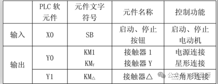
1. Circuit Design PLC wiring diagram and ladder diagram are shown in the diagram below:
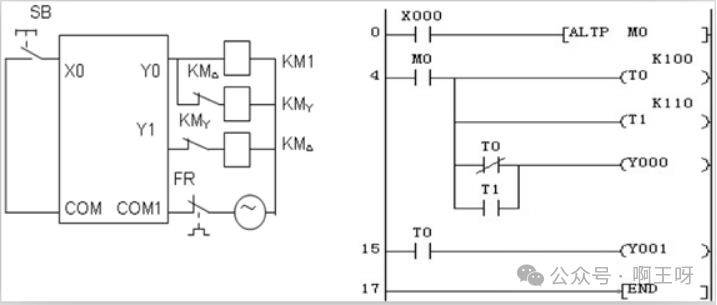
2. Control Principles Press the start button SB, M0=1, T0, T1 are energized, Y0 is energized, the contactor KM1, KMY are energized, and the motor M is connected in a star configuration for voltage reduction starting; the timer T0 is energized with a delay 10s, T0 normally open contact disconnects Y0 coil, KM1, KMY lose power, their main contacts disconnect, connecting Y1 coil, when KMY main contact disconnects, KMY normally closed contact closes, KM △ coil is energized, KM △ main contact closes, during this time there is an arc extinction process. Since KM1 loses power, KM △ main contact will not generate an arc, after a delay of 1s, Y0 is energized, KM1 is energized, connecting the motor M for delta connection at full voltage operation. Pressing SB, M0=0, Y0, Y1 are de-energized, stopping the motor. If the motor is overloaded, the thermal relay operates, disconnecting PLC output power, disconnecting the contactor’s power supply, stopping the motor. 4. Conclusion In PLC programming, several issues must be noted: The basic instructions and functions of PLC must be understood and mastered; programming should consider practical issues, be realistic, and have engineering significance; in the motor’s Y-△ voltage reduction starting circuit, the AC contactors KMY, KM △ must be interlocked. Since the computer executes the program at a scanning speed far exceeding the switching speed of the contactors, the PLC signal scanning process is very short, and the contact action is completed instantaneously (the execution cycle of Y1 instruction is 20ms), while the contactor’s disconnection and engagement have action times. During the action of switching the motor from Y to △, the switching of Y2, Y1 is very fast, but the contactor’s action always lags behind the PLC contact’s operation. When KM △ has not completely disconnected, Y1 contact has already allowed KMY to engage, resulting in a short circuit. Therefore, in addition to logical interlocking in the program, physical devices must also have interlocking; otherwise, it may lead to both AC contactors being energized simultaneously, causing a phase-to-phase short circuit in the power supply. The programmed logic should be thoroughly reviewed and debugged to optimize the program.
Note: The material is sourced from online compilation for learning purposes. If you are interested in PLC, you can follow the public account.