This article uses the Soldier300 V2 as an example to explain the EtherNet/IP (EIP) communication operations between the Newland Industrial Barcode Scanner and the Huichuan AC702 PLC.
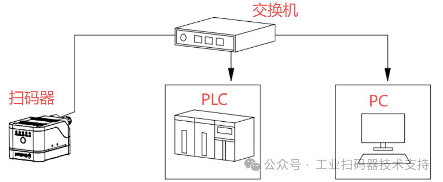
Connection Diagram:
Environment
PLC: Model AC702, accompanying software InoProShop
Barcode Scanner: Model Soldier300 V2, accompanying software NSet
DEMO: HuichuanEIP.project
EDS File: opener_sample_app.eds
Settings on the Barcode Scanner Side
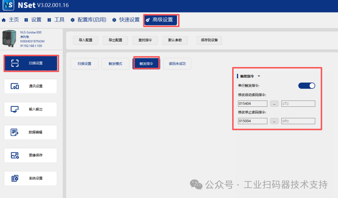
1. After entering the device in NSet, click on “Advanced Settings → Scan Settings → Trigger Command” to enable the serial trigger command.
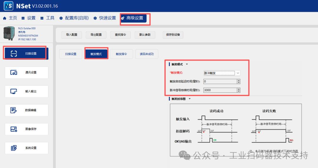
2. In “Advanced Settings → Scan Settings → Trigger Mode”, enable the pulse trigger.
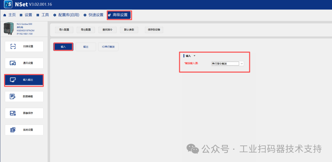
3. Click “Advanced Settings → Input/Output → Input”, and select serial command trigger as the input source.
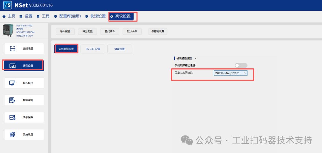
4. Click “Advanced Settings → Communication Settings → Output Channel Settings”, and select the industrial Ethernet protocol to enable the EtherNet/IP protocol.
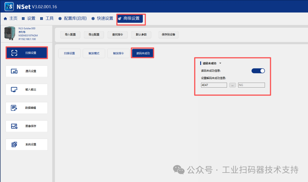
5. Click “Advanced Settings → Scan Settings → Read Code Unsuccessful”, and enable the read code unsuccessful information.
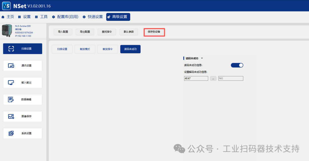
6. Finally, click [Save to Device].
Settings on the PLC Side
First, we need to confirm that the IP address of the PLC and the barcode scanner are in the same subnet. If they are not in the same subnet, one side needs to be changed to ensure both IP addresses are in the same subnet.
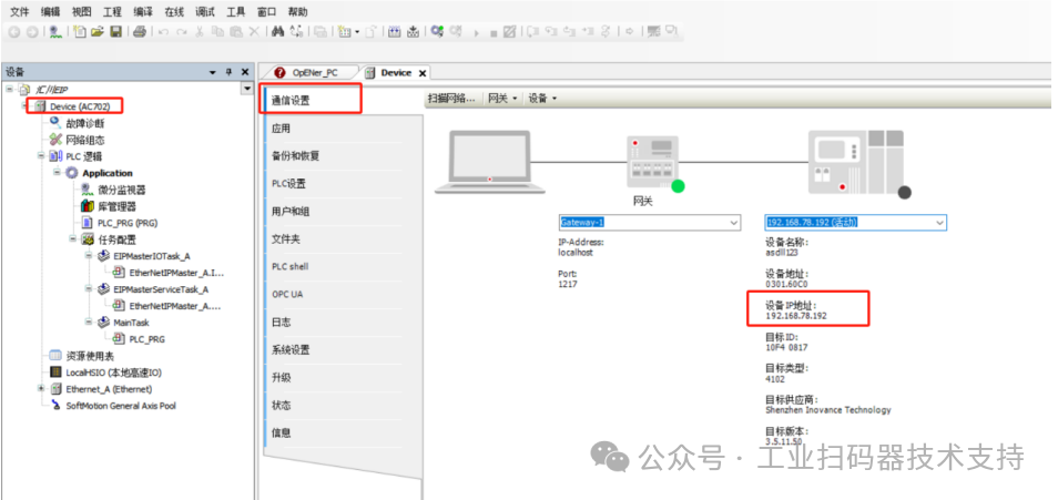
In this example, the IP of the Huichuan PLC is set to: 192.168.78.192, and the configuration in the DEMO is based on this, so the PLC’s IP address needs to be changed accordingly.
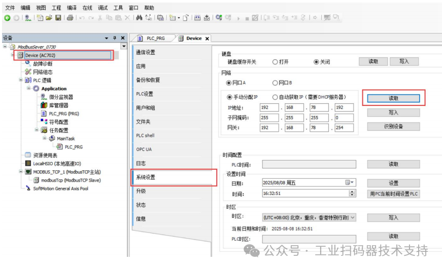
To check the PLC’s IP address, follow these steps:
Open InoProShop → In the left navigation pane, double-click Device (AC702), click Communication Settings, and you can view the PLC device’s IP address.
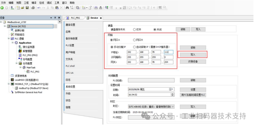
If you need to change the PLC’s IP address, you can do so by clicking Device (AC 702) – System Settings – Network, and modify the PLC’s IP address here.
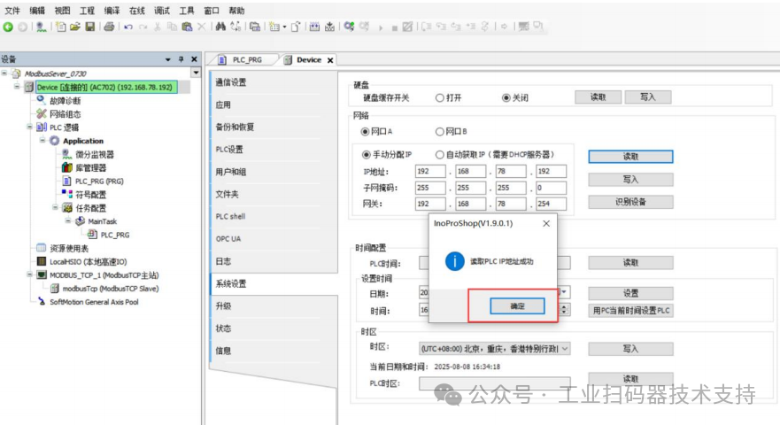
1. Click [Read] to obtain the current PLC’s IP address.
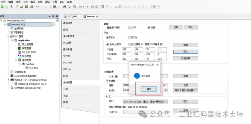
2. Enter the new IP address you want to modify, and then click [Write]. The new IP address will take effect after a successful write.
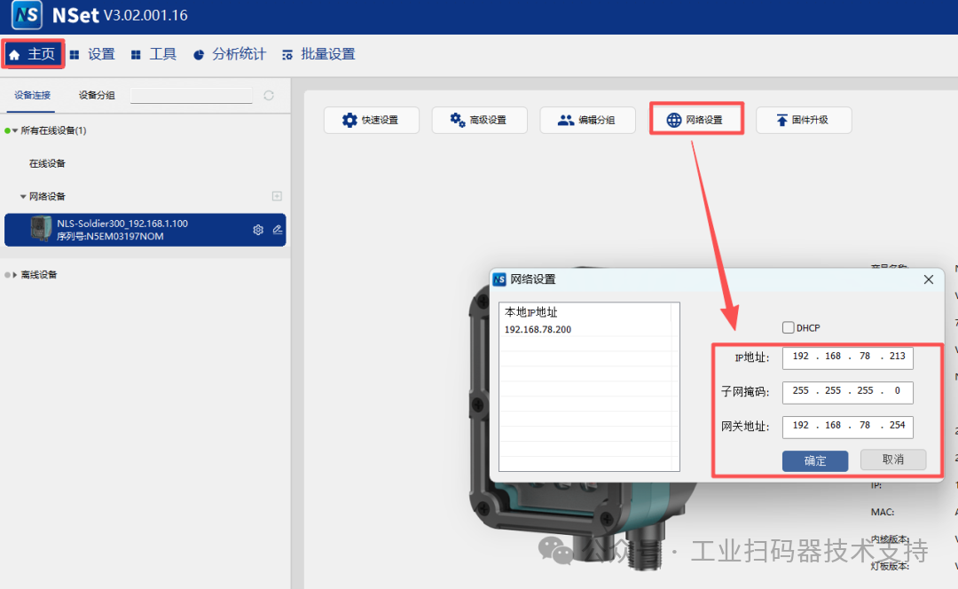
The default IP of the Newland Industrial Barcode Scanner is: 192.168.1.100.
For convenience in subsequent operation instructions, we will set the barcode scanner’s IP address to 192.168.78.213, which is in the same subnet as the PLC.
In the NSet software [Home] → [Network Settings], change the IP of the barcode scanner as follows:
Testing the DEMO Usage
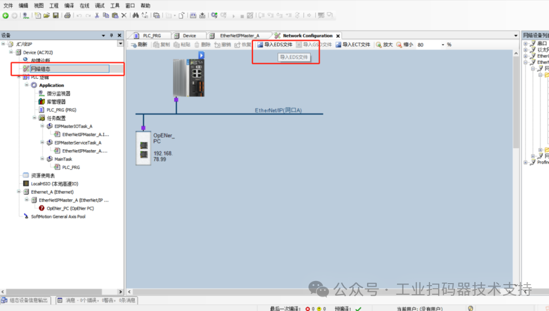
When using the EIP protocol, the EDS file must be imported, which can be obtained from the relevant technical support personnel at Newland.
Warm Reminder:
1. This test demo has already integrated the EDS file, so no additional import is required..
2. For users who are using the Newland Industrial Barcode Scanner and Huichuan PLC for EIP communication for the first time, it is recommended to first import this demo, as debugging in this environment makes it easier to understand the communication logic between the scanner and the PLC, and subsequent expansions can be based on this.
Next, we will detail the usage of the test DEMO.
1. Import the demo: HuichuanEIP.project ( )
)
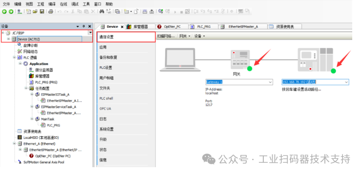
2. Check if the PLC is connected to the computer.
Click “Huichuan EtherNet/IP → Device → Communication Settings”,
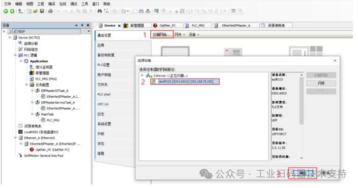
If the page shows two green dots as shown below, it indicates that the PLC is connected to the computer normally.
If the page shows a red dot, it indicates that the PLC is not connected to the computer and needs to be reconnected..
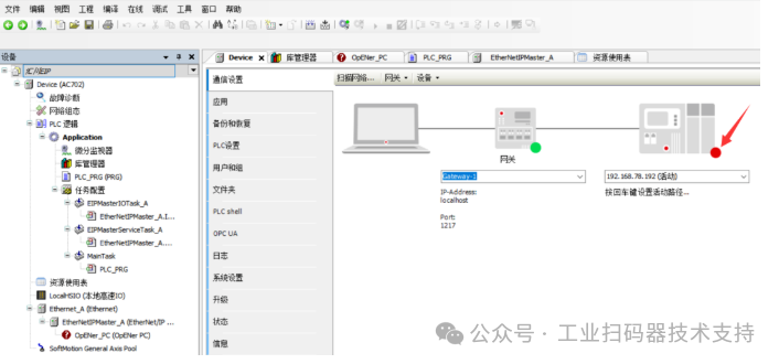
To reconnect: Click “Scan Network – Select the corresponding device, such as ‘asdIl123 [0301.60C0] [192.168.78.192]’ – Confirm”.
3. Log in to the device.
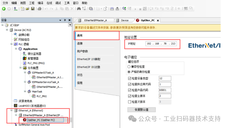
Double-click “Ethernet_A (Ethernet) – OpENer. PC (OpENer PC) – General – IP Address, enter the barcode scanner IP, such as 192.168.78.213”.
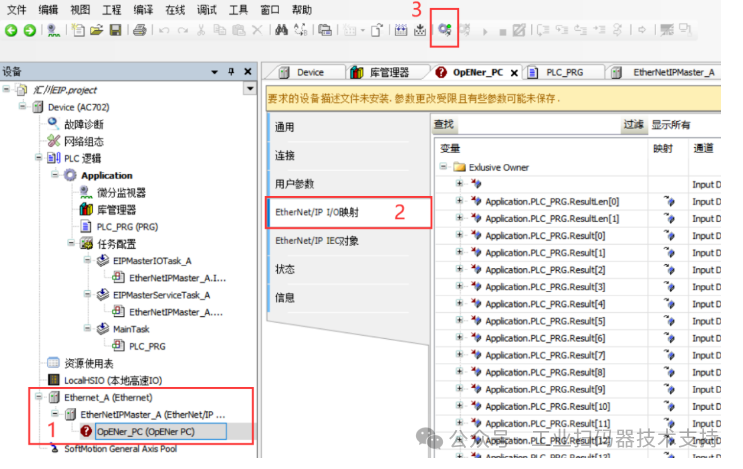
Click “Ethernet_A (Ethernet) – OpENer. PC (OpENer PC) – EtherNet/IP I/O Mapping – Log in – Select ‘Yes'”
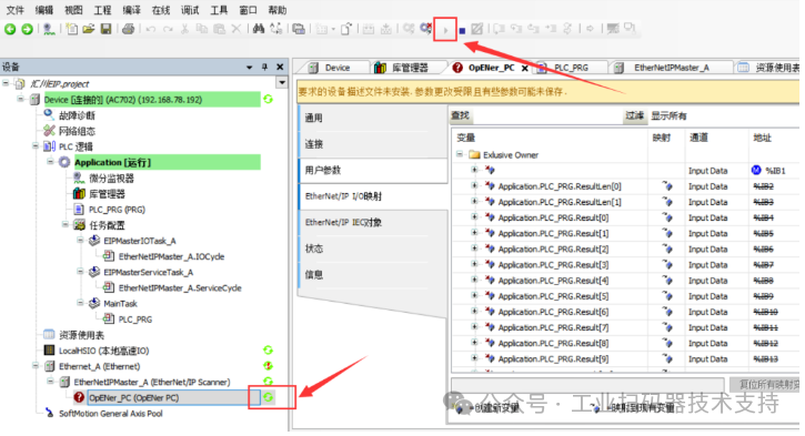
4. Trigger the code reading.
Click the triangle icon in the image below to trigger the start of code reading, and click the square icon
 to stop the current operation.
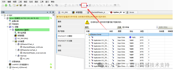
The appearance of a green indicator in the left taskbar indicates that the PLC has successfully triggered, as shown in the image below:
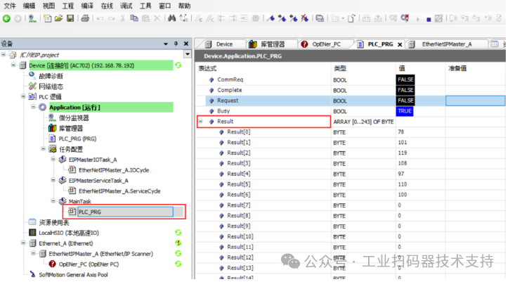
5. View the code reading data.
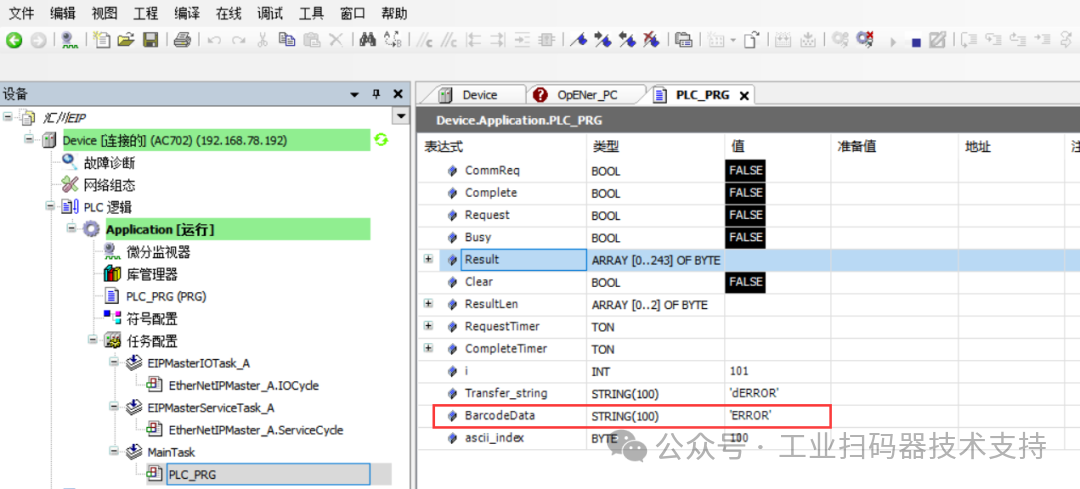
Double-click “PLC Logic – Application [Running] – Task Configuration – PLC_PRG – Result” to see the decimal code reading result.
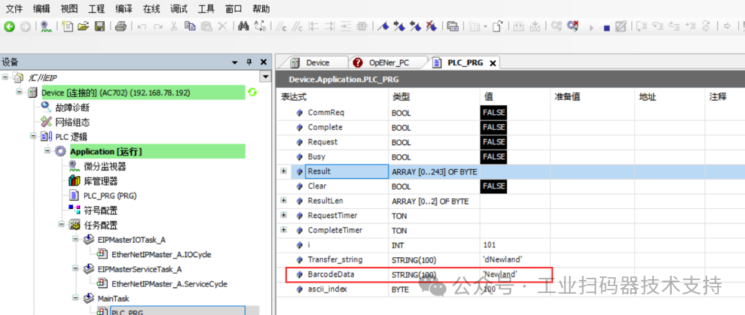
Click “BarcodeData” to see the string reading result..
If the device fails to scan the code during the trigger process, it will output an error messageERROR (fixed value).
Click “PLC Logic – Application [Running] – Task Configuration – PLC_PRG – Result” to see the decimal reading result as69, 82, 82, 79, 82 (the corresponding character combination isE, R, R, O, R).
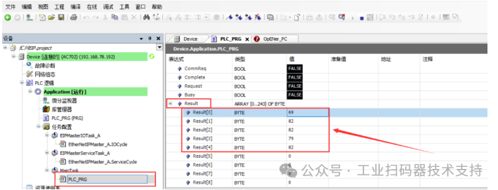
Click “BarcodeData” to see the string reading result asERROR..
Please open in the WeChat client