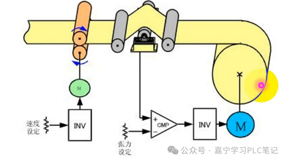
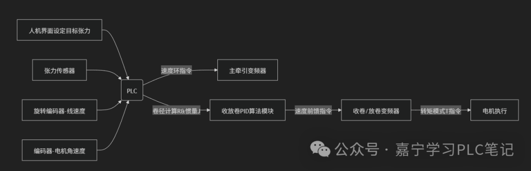
 In the field of industrial automation (especially in industries such as printing, film, and cables), tension control during winding and unwinding is one of the core technical challenges.Tension control is a core technology in winding equipment (such as printers, coating machines, drawing machines, and slitting machines).The main goal is to maintain a constant material tension during dynamic processes such as varying roll diameters, acceleration and deceleration, and changes in material elasticity. This ensures that materials (such as paper, film, and metal wire) maintain stable tension during winding or unwinding, avoiding slack, stretching, or breaking.Tension control algorithms typically combine PLC programming, servo motors or variable frequency drives, sensors (such as tension sensors or diameter sensors), and control logic.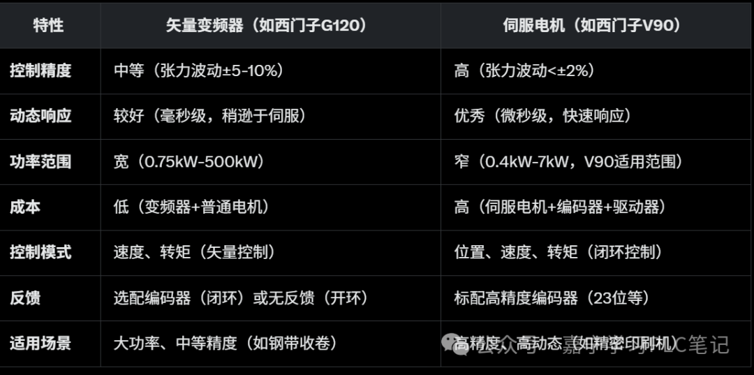
- Advantages of Vector Variable Frequency Drives:
- Low cost, suitable for high-power or budget-limited projects.
- Simple hardware, easy maintenance, suitable for harsh environments (such as high temperatures and dust).
- Supports open-loop control, reducing sensor costs.
- Advantages of Servo Motors:
- High precision and high dynamic response, suitable for complex processes.
- Closed-loop control, strong anti-interference, and high stability.
- Supports multi-axis synchronization (such as PROFINET Telegram 7/9).
- Selection Criteria:
- Precision Requirements:Tension fluctuation <±2%, choose V90; ±5-10% acceptable, choose G120.
- Power Requirements:>7.5kW use variable frequency drive, <7.5kW can use servo.
- Budget:Choose variable frequency drive for low cost, choose servo for high performance.
1. Using Vector Variable Frequency Drives for Winding Control
Principle: Vector variable frequency drives use Vector Control technology to precisely control the motor’s magnetic field and torque, similar to the current loop and speed loop control of servo motors, providing high dynamic response and torque accuracy. It acts like a “smart” speed controller that can not only control how fast the motor turns but also how much torque it produces, suitable for scenarios requiring tension control.
Capabilities: Supports speed control and torque control, suitable for tension adjustment during winding and unwinding.
Can be controlled via PLC communication (such as PROFINET, Modbus) or analog signals (0-10V/4-20mA). It has a wide power range (0.75kW to several hundred kW), suitable for high-load scenarios.
Applicable Scenarios:Medium precision requirements: such as winding and unwinding of paper, plastic film, and textiles, with tension fluctuations allowed at ±5-10%.High power loads: such as winding of metal coils and steel strips, with power requirements exceeding those of servo motors (e.g., >7.5kW).Cost-sensitive projects: Vector variable frequency drives are cheaper than servo systems, suitable for budget-limited non-standard automation.
Practical Case
- Scenario:Paper winding machine, target tension 50N, roll diameter 0.1m-0.6m, line speed 15m/min.
- Hardware:S7-1200 + G120 (3kW) + tension sensor (0-100N, 4-20mA).
- Algorithm:Closed-loop control (tension sensor + PID).
- Implementation:
- Configure G120: p0922=3, p1300=22.
- PLC calls PID_Compact, SP=50N, PV read from SM1231, Kp=3, Ki=0.8.
- Send torque setpoint via PROFINET, p1520=150%.
- Update tension every 10ms, monitor fluctuations.
2. Servo Motor + Tension Control Algorithm
Objective:Maintain constant tension of materials during winding or unwinding processes.
During winding (or unwinding), the material cannot be too loose (slipping) or too tight (breaking), and must maintain “just the right amount of pull”.Core Elements:Tension Source: Controlled by the winding motor (torque output) or the resistance of the unwinding motor.Feedback Mechanism: Real-time tension or status feedback through tension sensors (force measurement) or diameter sensors (measuring roll diameter changes).Control Method: PLC adjusts the torque and speed of the servo motor (or variable frequency drive) through algorithms to maintain stable tension.Control Types:Open-loop Control: No tension sensor, tension controlled based on roll diameter calculations or empirical values, low cost but limited precision.Closed-loop Control: Uses tension sensors for real-time feedback, dynamically adjusting torque or speed, high precision.2.1 Open-loop Tension Control (Based on Roll Diameter Calculation)
Tension is provided by the motor torque, torque formula: T = F × R (T is torque, F is tension, R is roll diameter). As winding (or unwinding) occurs, the roll diameter R changes, requiring dynamic adjustment of torque T to maintain constant tension F. The roll diameter can be obtained through encoders, diameter sensors, or calculations (based on line speed and time).
Like rolling a towel, as the towel rolls up, the roll diameter increases (R increases), and you need to apply more force (torque) to keep it tight. The PLC calculates the required torque based on the roll diameter changes and instructs the servo motor to output the appropriate force.Applicable Scenarios: Low-speed, low precision requirements. Low-cost equipment, such as small slitting machines or simple winding machines.
Advantages:No tension sensor required, low cost. Suitable for simple processes or low tension requirements.
Disadvantages: Low precision, easily affected by material thickness and friction changes. Cannot respond to sudden tension changes (such as material slipping).
- Obtaining Roll Diameter:
- Method 1: Diameter sensors (such as ultrasonic or laser) directly measure roll diameter.
- Method 2: Calculate using line speed (V) and rotational speed (n):R = V / (2πn).
- Method 3: Estimate based on material thickness (h) and number of turns (N):R = R_0 + h × N(R_0 is the initial roll diameter).
- Calculating Torque:
- The tension setpoint F (in N) is given by the process.
- Real-time torque:T = F × R.
- Considering friction and losses, add a compensation factor:T = F × R × K(K is the compensation factor, usually 1.1-1.5).
Dynamic Adjustment:Every certain period (e.g., 10ms) update roll diameter R and recalculate T.
2.2 Closed-loop Tension Control (Based on Tension Sensors)
Tension sensors (such as pressure sensors or load cells) measure material tension in real-time and feed back to the PLC. The PLC compares the actual tension with the set tension using a PID algorithm and adjusts the torque or speed of the servo motor.Like using a spring scale to pull a rope, the scale tells you the pulling force (tension) in real-time, and the PLC adjusts the motor’s “force” or speed to maintain constant pulling force.
Applicable Scenarios: High-precision equipment, such as printers, coating machines, and metal drawing machines.
Advantages: High precision, can respond to tension changes in real-time. Suitable for high precision and complex processes.Disadvantages: Requires tension sensors, high cost. PID tuning is complex and requires experience.
Principle: Real-time detection of tension F_actual through tension sensors (such as tension pendulums, weighing rollers, ultrasonic sensors), comparing with set value F_set, and dynamically adjusting the drive output using PID algorithm. Error = F_set – F_actual
PID_Output = Kp·Error + Ki·∫Error·dt + Kd·d(Error)/dt → Control variable frequency drive output frequency/servo torque
- Obtaining Tension Feedback:
- Tension sensor outputs an analog signal (such as 4-20mA or 0-10V), connected to the PLC analog input module (such as S7-1200’s SM1231).
- Convert the analog signal to tension value (in N), calibration of sensor range is required.
- PID Control:
Call the PID_Compact function block (FB68) in TIA Portal, set:
- Setpoint (SP):Target tension (e.g., 50N).
- Process Value (PV):Actual tension feedback from the tension sensor.
- Output (MV):Control torque or speed of V90.
PID Parameters:
- Kp (Proportional Gain): Controls response speed, initial value can be set to 1-5.
- Ki (Integral Gain): Eliminates steady-state error, initial value set to 0.1-1.
- Kd (Derivative Gain): Suppresses oscillation, initial value set to 0 or a small value.
- Control Output:
- Torque Mode:Send torque setpoint to V90 via Telegram 750, adjust p1470 (current loop gain).
- Speed Mode:Send speed setpoint via Telegram 1/3, adjust p1470 (speed loop gain).
- Dynamic Adjustment:
- PLC runs PID every cycle (e.g., 10ms) to update output.
- Monitor tension fluctuations, fine-tune Kp/Ki/Kd to prevent overshoot or oscillation.
2.3 Hybrid Control (Roll Diameter + Tension Sensor)
Combining open-loop (roll diameter calculation) and closed-loop (tension sensor), using roll diameter to estimate initial torque and correcting deviations with tension sensors. Roll diameter provides coarse adjustment, while tension sensors provide fine adjustment. Like driving a car, first estimating the route with navigation (roll diameter calculation), then fine-tuning the direction based on road conditions (tension feedback), ensuring both speed and accuracy.Advantages: a. High precision and strong robustness, adaptable to complex working conditions. b. Even if the sensor fails, open-loop serves as a backup. b.Significantly improves dynamic response speed, reducing tension shocks.Disadvantages: System complexity, long debugging time. High hardware costs (requires sensors and computing modules).Algorithm Steps:
- Initial Torque (Open-loop):
- Same as open-loop control, calculate:T = F × R × K。
- Send initial torque to V90 via Telegram 750.
- Tension Correction (Closed-loop):
- Tension sensor feedbacks actual tension, input to PLC’s PID_Compact.
- PID output corrects torque (ΔT), added to initial torque:T_total = T + ΔT。
- Dynamic Update:
- Update roll diameter R and tension feedback every cycle, adjust T_total.
- Optimize V90 parameters: p1520 (torque limit), p1470 (current loop gain).
3. Formulas:
Given: Core diameter d, material width b, material thickness h, reduction ratio i, servo speed n, set tension to determine servo torque,
Servo operates in torque mode to control the size of the servo torque,
Torque is divided into three parts: 1. Material tension torque 2. Friction compensation torque 3. Acceleration and deceleration inertia compensation torque
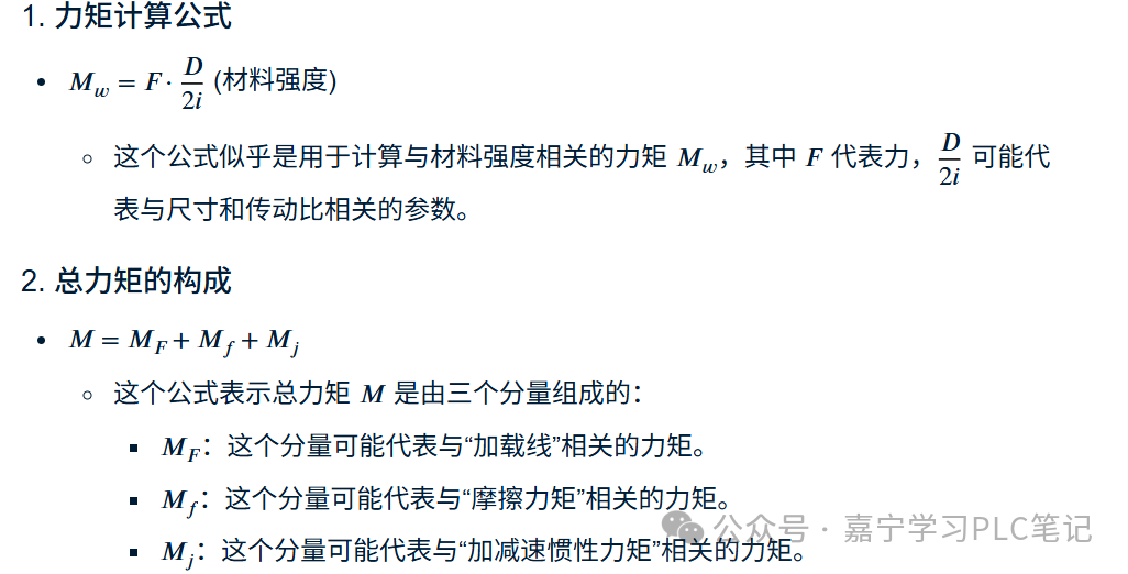
3.1 Tension Calculation Tension Calculation:
Tension F = Width b * Thickness h * Material tension given value f
b
Tension F = Torque T / Roll Diameter R (Controller calculates the required motor output torque based on the current roll diameter R T (T = F × R))
Torque Formula:T = F × R(T is torque, F is tension, R is roll diameter)
3.2 Roll Diameter Tracking AlgorithmMethod 1: Line Speed Differentiation Method
-
R = (V × dt) / (Δθ × G)
Where:
  V = Material line speed (front encoder)
  Δθ = Increment of winding motor angular displacement
  G = Reduction ratio
-
Method 2: Diameter Layer Accumulation Method(Applicable for regular rolled materials)
<span>R_current = R_0 + (2π·N)·thickness</span>
3.3 PID Parameter Self-tuning Dynamically adjust PID parameters based on roll diameter R and system inertia J:
Kp = Kp0 × √(J/J0)
Ti = Ti0 × (J/J0)   // Integral time constant
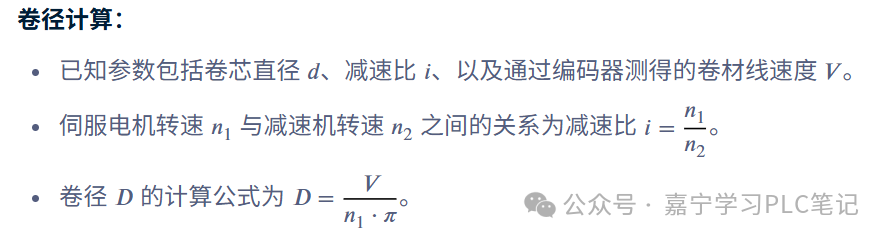
3.4 Other Parameter Calculationsd roll diameter (known), n1 servo motor speed, n2 speed from the reducer, calculate ratio i (servo motor speed n1 to reducer speed n2
)Material line speed V(V= n1πD/i)Roll diameter D calculation formula is