The analog input and output control of Siemens PLC has a wide range of applications in the field of industrial automation. This article will provide a detailed introduction to the applications of Siemens PLC analog input and output control, including instruction introduction, programming methods, hardware connections, and common issues.
In industrial control, the processing of analog signals is crucial. The analog input and output control function of Siemens PLC is powerful and can meet various complex control requirements. Analog signals include continuously varying physical quantities such as temperature, pressure, liquid level, and flow, which need to be converted into electrical signals through specific sensors and transmitters, and then collected and processed by the PLC.
The analog input and output control of Siemens PLC involves two important instructions: normalization instruction and scaling instruction. The normalization instruction is used to map the input value to a linear scale for normalization, making it fall between 0.0 and 1.0. The scaling instruction is used to calibrate the normalized value back to a specific range between a minimum and maximum value. Understanding these two instructions is crucial for writing analog programs.
Next, we will detail the applications of Siemens PLC analog input and output control from the aspects of hardware connection, programming methods, and common issues.
1. Normalization and Scaling Instructions
(1) Normalization Instruction
The normalization instruction of Siemens PLC is used to standardize the value within the range specified by the minimum and maximum values, calibrating it to be between 0.0 and 1.0.
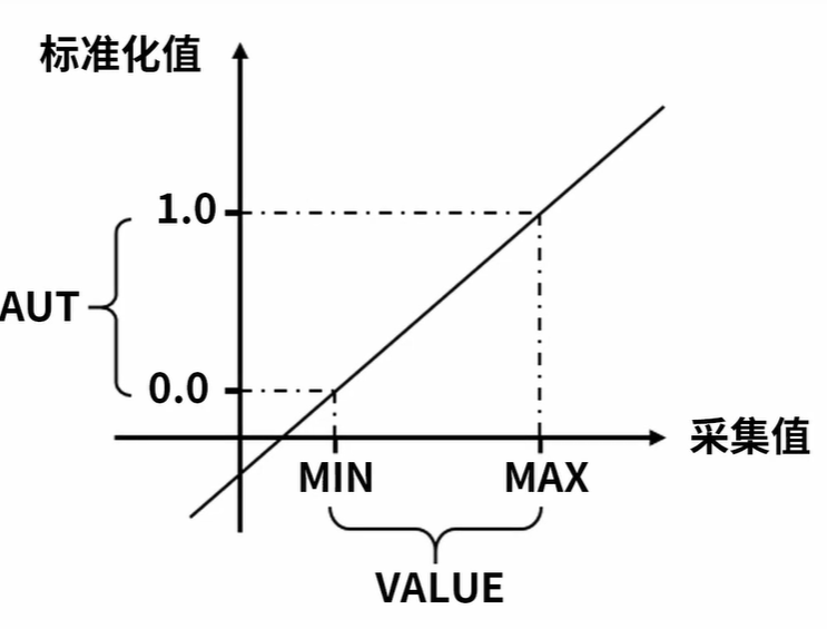
The calculation formula is OUT = (VALUE – MIN) / (MAX – MIN). For example, when we need to process an analog signal, suppose the input value VALUE is a specific value, and the minimum value MIN and maximum value MAX are the specific range limits.
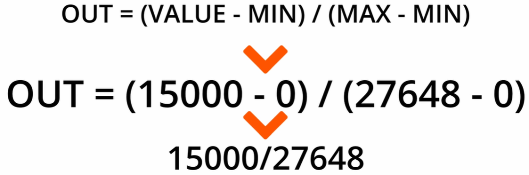
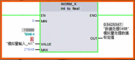
For example, when processing the signal from a temperature sensor, suppose the signal range output by the temperature sensor corresponds to a value range in the PLC from 0 to 27648. When the input value is 15000, substituting into the formula gives: OUT = (15000 – 0) / (27648 – 0) = 0.5425347. Through such normalization processing, we can unify different ranges of analog signals to the standardized interval of 0.0 – 1.0, facilitating subsequent processing and calculations.
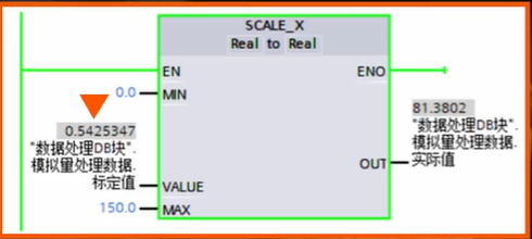
(2) Scaling Instruction
The scaling instruction is used to calibrate the values specified by the minimum and maximum values, mapping the data between 0.0 and 1.0 to the range between the minimum and maximum values.
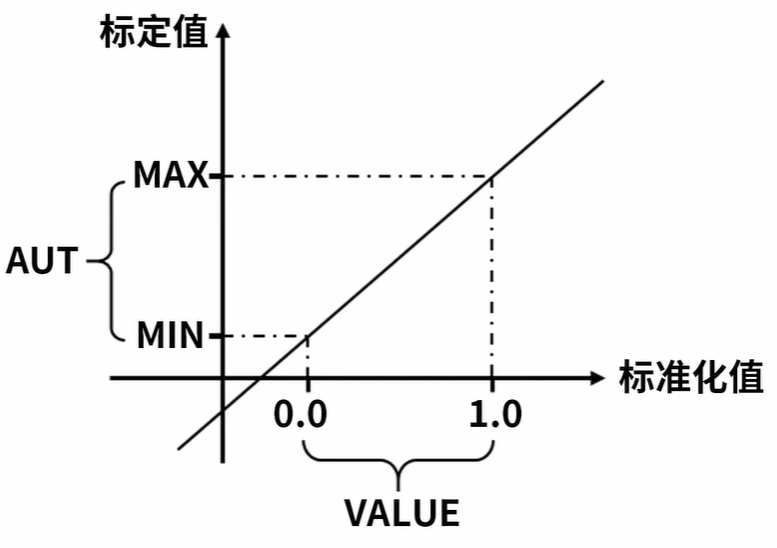
The calculation formula is OUT = VALUE * (MAX – MIN) + MIN.
For instance, when processing the temperature signal, the normalized value value is 0.5425347, and the temperature sensor’s range is 0 – 150, with the minimum value being 0 and the maximum value being 150. Substituting into the formula gives: OUT = 0.5425347 * (150 – (0)) = 81.3802. This way, the normalized value is calibrated back to the actual temperature range, allowing us to obtain a specific temperature value.
2. Analog Input Programming
(1) Hardware Connection
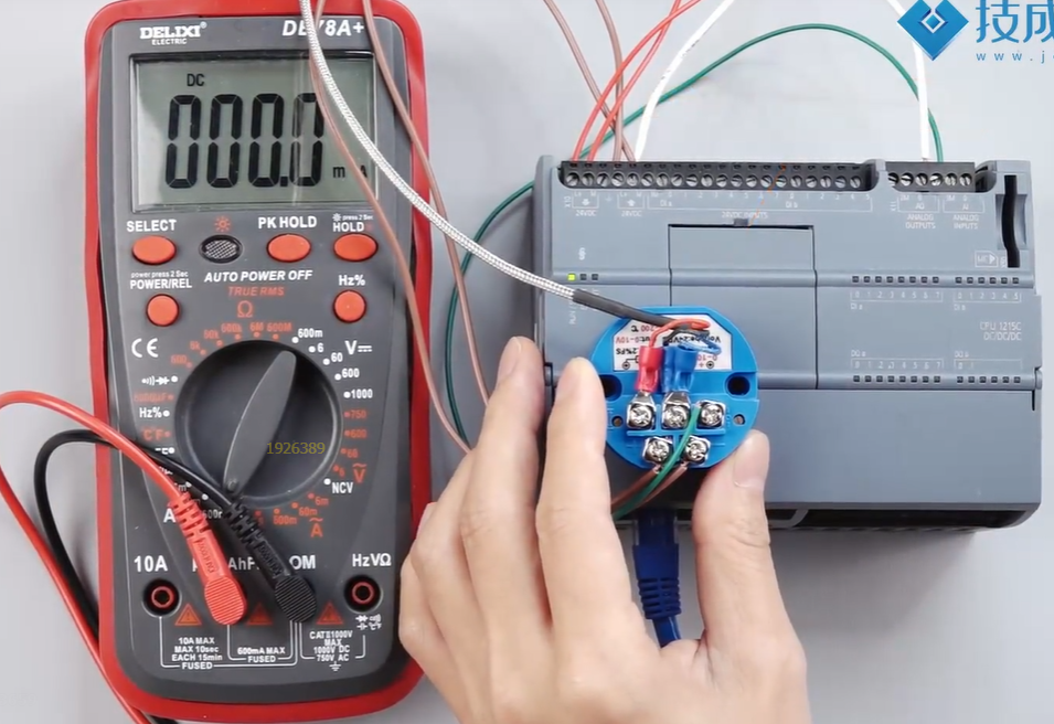
Connect the analog input signal to the PLC through an analog input module. In practical applications, for example, a sensor outputs a signal of 0 – 10 volts, the output signal of the sensor is usually connected to the PLC’s analog input module through specific wiring. Specifically, there will be two wires connecting the sensor to the PLC to achieve the transmission of the analog signal.
(2) Programming Implementation
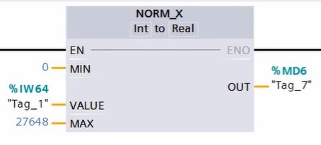
In the programming process, first drag out the normalization instruction. For a 0 – 10 volt sensor signal, since its corresponding value range is from 0 to 27648, fill in 0 for the minimum value and 27648 for the maximum value on the left pin of the normalization instruction. The VALUE pin should be filled with the channel address where the sensor signal is connected, for example, IW64. The normalized value is stored in a specified address, such as MD6. This completes the normalization processing of the input signal.
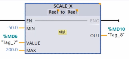
Next, drag out the scaling instruction. Since the sensor’s range is a specific range, for example, -50 – 200°, set the minimum value to -50 and the maximum value to 200 in the scaling instruction, with the VALUE being MD6, which is the normalized value. Finally, store the converted actual temperature value in a specified address, such as MD10. Here, select the data type as floating point, because the final temperature value needs to have a decimal point to accurately reflect the actual physical quantity.
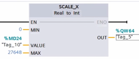
3. Analog Output Programming
Taking the example of controlling a frequency converter to run at 0 – 50Hz, we will introduce the programming method.
Drag out the normalization instruction and set the parameters to normalize the given frequency value.
First, we will drag out the normalization instruction. Since we want to control the frequency range of the frequency converter from 0 – 50Hz, and the frequency may be a floating-point number with decimals, such as 35.2, 32.6, etc., we fill in the minimum and maximum values as 0.0 – 50.0. The VALUE pin is filled with an address, such as MD20, which is the frequency value we want to set. The normalized value is placed in MD24.
Then, drag out the scaling instruction, set the parameters to convert the normalized value to the analog output value, controlling the output of the frequency converter.Next, we will bring out the scaling instruction. Place MD24 into the VALUE pin. Since the corresponding current value is 0 – 20mA, the maximum and minimum values are 0 – 27648. Finally, place the data in QW64 to achieve control of the frequency converter. Through this programming method, we can accurately control the output frequency of the frequency converter according to actual needs, meeting different industrial control requirements.
Thought Questions and Explanations
Question 1: The calculation formula for the normalization instruction is ( )
Explanation: The calculation formula for the normalization instruction is
OUT = (VALUE – MIN) / (MAX – MIN)
Question 2: The calculation formula for the scaling instruction is ( )
Explanation: The calculation formula for the scaling instruction is
OUT = VALUE * (MAX – MIN) + MIN.
Scan the QR code below to watch related courses